Transcripts
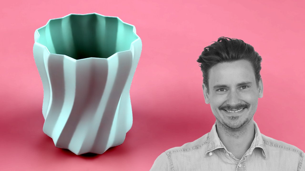
1. Autodesk Fusion Class Introduction: Welcome to this parametric
lampshade project. For those of you
who don't know me, I'm Martin, a
landscape engineer, a professional in
the AEC industries, a university CAD
teacher, and a maker. I use Autodesk Fusion a lot in
my side business. I create physical items
for my ETSY business, classes on this platform, and I also post
tutorials on YouTube. My first experience
with CAD software was a landscape engineering
project about ten years ago. We probably made a two dimensional bench or
something like that. I work with different
CAD software on a regular basis,
and Autodesk Fusion, the CAD software you
learn more about in this project is the CAD software I'm most passionate about. The opportunity to cover
the entire process from design to manufacturing
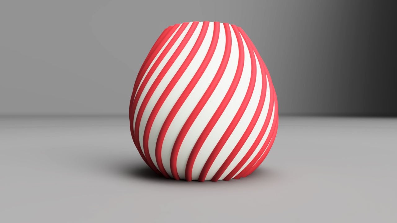
within one program is amazing. In this project, we mix some fundamental Autodesk Fusion techniques into a smooth and easy workflow and create a
parmetric lampshade. Working with parameters has many advantages as you will
see throughout the project. Everyone is on a personal track on their 3D modeling
learning journey. The lessons are divided
into short segments, so it will be easy for
you to find, watch and rewatch relevant parts on your computer or why
not on your phone. I hope to see you
in the next lesson where we talk more about
your project assignment. Thank you.
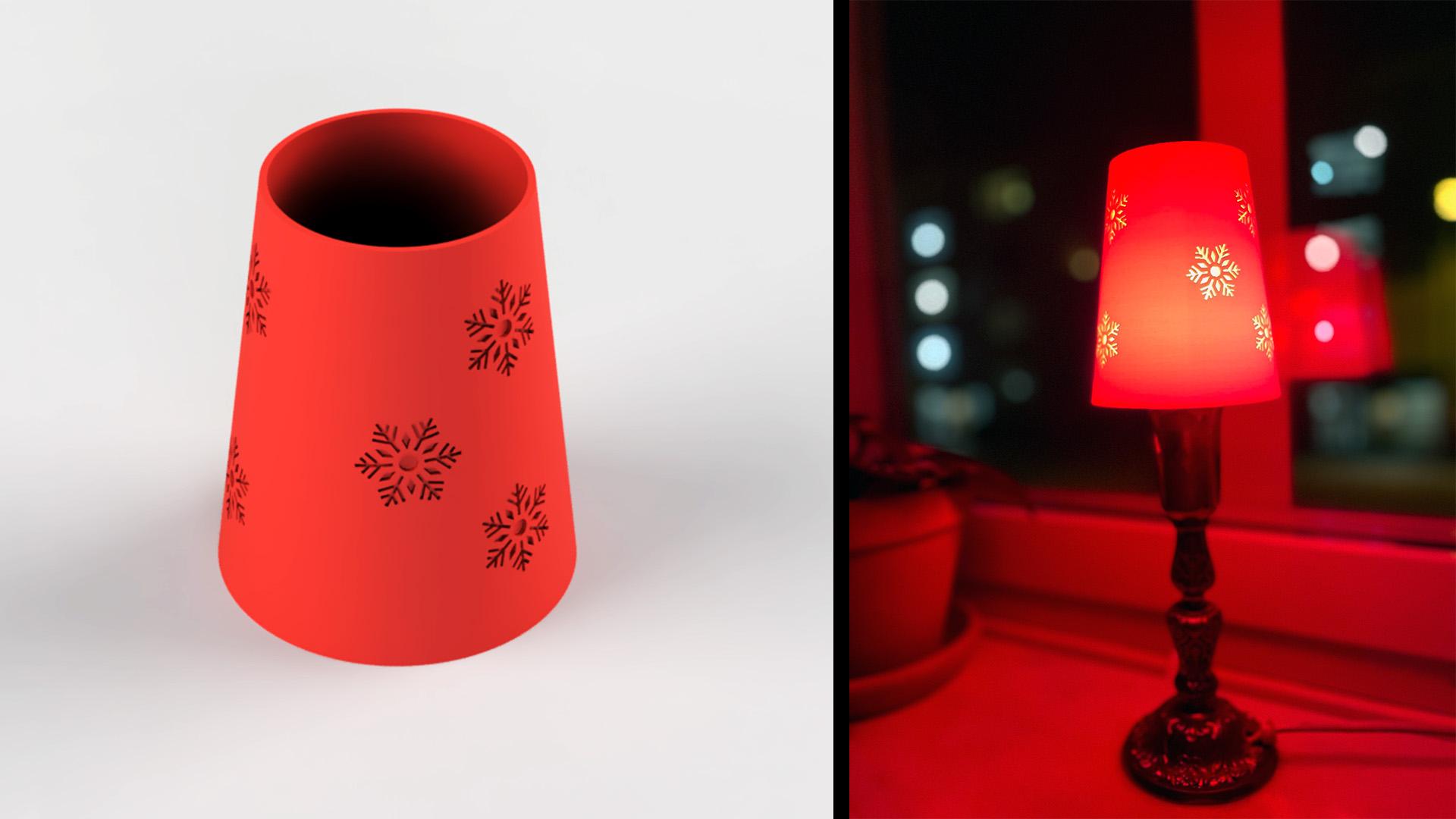
2. Project Assignment: Your project assignment
is to upload a photo of your parametric lampshade
to the project gallery. You can either upload
a real picture of your 3D printed design or why not a digital photo of your
Autodesk Fusion rendering. Your lampshade should
have a pattern and an angle between
the top and the bottom. Be sure to keep a
safety marginal between your lampshade
and your lamp, so you don't cause an accident. I'll do my best to leave
feedback on your work and look forward to seeing your creative ideas
posted online. See you in the next
lesson, where we will follow the first rule of Autodesk Fusion. Thank you.
3. Save your project and create a component: Give yourself a good start
and save your project. After that, open
design shortcuts with keyboard shortcut S and
search for new component. The first rule of
Autodesk Fusion is to work with components. This best practice
has many benefits. Some examples are the
ability to collect actions that belong to
the same component in the same timeline
and the ability to assemble components into
a finished product. Give you component
a logical name and make sure to activate it. We have started the
project in a great way. See you in the next lesson
where we set up some user parameters. Thank you.
4. Set up Parameters in Autodesk Fusion: If I could go back in time and change one thing on my
Autodesk Fusion journey, then I'd start working
with parameters earlier. If you're new to parameters, just trust me that this will make sense as you proceed
with your project. I want to set up a design, and I want to be able to change the size of the
entire design with just a few actions while I keep the ratios of different
product dimensions. The dimensions I
use for my project are from a good looking lamp
shade I have in my home. You can use other dimensions
for your project. Press plus and start with
your first parameter. I will name this Fusion
parameter bottom and give it a dimension
100 millimeters. I'll name the second
parameter Top. The expression will
be bottom times 0.7. I'll name my third
Parameter height. The value will be
bottom times 1.2. My fourth parameter will
be called basefoot. This one is fixed at 37 millimeters since the
lamp shade must fit the lamp. You'll see what I mean when we proceed with the project
in the coming lessons. The fifth perimeter
is called thickness, and I set this to 2 millimeters. Just like the fourth parameter, this parameter has no relation to the first three parameters. The sixth parameter
is called emboss. I'll set this as
thickness times 0.7, and I'm just exploring here. I could have set this
thickness two times 0.8 or 0.6 or 0.5 as well. Those are our parameters, and it's okay if
you're confused. You'll see why we did this soon. But first, see you in the
next lesson where we set up a new construction
plane. Thank you.
5. Create a construction plane in Autodesk Fusion: You're taking a class on a
3D printed lampshade and we have not even started
on the lampshade sketch. Instead, we create components, set up parameters, and now a construction plane.
You might wonder why. The reason is because we want
to be able to create, edit, and make variations of the lampshade with
very few actions. So, onto the construction plane, we'll make an offset
plane and we'll set the height to our user
parameter height. You now have two different
construction planes at a distance equal to
the user parameter height. Let's make some sketches in
the next lesson. Thank you.
6. Sketch with user Parameters in Autodesk Fusion: It's tempting to press the sketch button in
the top left corner, but the Pro Tip is to activate design shortcuts with
keyboard shortcut S. Search for sketch and select the construction plane
for your sketch. Press keyboard shortcut C to activate the circle commando. The blue infill indicates
that circle is activated. Start your circle
in the center of the canvas and set the
dimension to basefoot. Create a second circle
and set the dimension to bottom, or whatever you call
your custom user parameter. Activate sketch shortcuts with keyboard shortcut S and
finish your sketch. Create a new sketch, but select the upper
construction plane this time. You see here why it was so convenient to sketch in
the center of the origo. You can place this circle on
top of the other circles. I'll use the user
parameter top for this circle and then exit a sketch environment via
the sketch shortcuts. We have about 80% of
our lampshade now, and we can't even see it. See you in the next lesson where we connect your circles. Thank you.
7. Loft in Autodesk Fusion: It's time to put the
pieces together. And this is obviously not the only way to
create this shape, but I recommend this
workflow because it's fast, precise, and as we will
see later, easy to edit. Loft is easy to use. Select your first and your second
profile to connect them. We'll keep it
simple in this tutorial and stick to this
new body operation. This body is created within
our active component, and that's perfectly fine. We've got a solid body which is based on
connected geometries. Let's take a closer look
in the next lesson and perform a section analysis on our 3D model. Thank you.
8. Section Analysis in Autodesk Fusion: You can activate
section analysis. Via the inspect drop down menu, but let's stick to our
fast workflows and activate design shortcuts
with keyboard shortcut S. You can perform your
section analysis flat or with an angle. You can immediately see that your lampshade needs to lose some material
from its inside. This is because we made the
shape with the loft command. If we, for example, used another workflow with focus on the revolt commando
to create or lamp shade, then we would not
have this situation. It's not really a
problem, though. Let's fix it with
the shell commando in the next lesson. Thank you.
9. Use the Shell Command in Autodesk Fusion: Let's get rid of the
inside of our lampshade. You find the shell commando in the modify section
of the tool bar, but I will activate design shortcuts with keyboard shortcut S
and take it from there. Use the blue option, which is for solid modeling, Give your body an inside
thickness and press OK. We're not completely done yet. We clearly see that
you won't be able to assemble this lamp shade since there's no
hole for the lamp. Do you remember the circles we
made in a previous lesson? Activate Extrude with
keyboard shortcut E and find this circle. You'll have to turn
your sketch visibility on if you can't find it. Once you press Extrude, you might be tempted
to add a distance. However, we would like
the extrude cut to follow along if we make a change to the
thickness of the design. Therefore, you should change
the extent type to all, so your extrude
cut operation will cut through the design when
you change the thickness. And that's it. See you in
the next lesson where we add another
construction plane. Thank you.
10. Add a Construction Plane at an angle: One of the design goals is to add a pattern on the lampshade, and we will add a construction plane as
a step in that process. Normally, I'd use
design shortcuts, but I want to show you where
to find the tangent plane. Once you select your face, the reference plane
becomes visible. We will leave it with a default setting since it
already has the right angle. We will use this
construction plane for our upcoming pattern. But first, let's pretend that we want to change the
size of our design, but keep all ratios intact. Let's look at parameters
again. Thank you.
11. Change user parameters in Autodesk Fusion: We set up parameters in the
beginning of the project. This will allow us to
change the size of our object and keep the
relations and ratios, such as the angle of
our design intact. Activate design shortcuts with keyboard shortcut S and search
for change parameters. We see that our top and our height are related
to our bottom. Our basefoot, which is
the hole needed to assemble the lampshade is fixed
at 37 millimeters. Our thickness is fixed
at 2 millimeters and we haven't used the
emboss parameter yet. When we change the
bottom, our lamp adjusts. You can right click
in the canvas and easily find your latest
commando and more. That's how easy it is to
work with parameters, and the opportunity to
create relations and equations is useful when you iterate and
edit your design.
12. Insert DFX File in Autodesk Fusion: You can either
sketch directly on your angular
construction plane or insert a DFX file
with a sketch. The purpose is to
create a sketch with the same angle as our lampshade. You'll find the DfX file I used for this project in
the project resources. Use it if you'd like to. Locate your DFX file on your computer and select
your construction plane. This pattern is too large
and we need to move it. We'll do this in two steps. See you the next lesson, where we move the
DfX file. Thank you.
13. Move your DFX File in Autodesk Fusion: You need to select
your move object, which is sketch objects in this case, before you
make your selection. When you drag from the right
to the left like this, everything you
touch is selected. Be careful here so you
don't make mistakes. You can see your selection
in the project browser. I just want to move the snowflake
pattern, but sketch one, which isn't named,
so we can't be sure what it is,
is also selected. A quick fix is to turn the sketch visibility off
and redo the selection. Going from the left to the right is different than going
from the right to the left. When you go from left to right, everything you completely
cover is selected. You can work with
different move types, such as free move or
point to point. Free move is pretty good
in this scenario. There is no right or wrong
place for your snowflake. We'll leave it here for now
and see you in the next lesson where you scale your DFX
file. Thank you.
14. Scale your DFX File in Autodesk Fusion: There is no exact size
for our snowflake sketch. Therefore, I prefer to scale, and not calibrate
in this scenario. You find scale in the
modify drop down menu or via
the shortcut paths
we've discussed earlier. I've seen people make
a common mistake here. When they try to
select their DFX file, they fail to select it. This is because our
DFX file is a sketch, and we change it in the
contextual sketch environment. Right click your sketch
and select sketch scale. Select your entities,
your center point for the scale operation,
and then either drag or type a scale factor. I'll type 0.25, which
means that I scale the sketch to a size which is 25%
of the original size. Activate Autodesk Fusion Sketch shortcuts with keyboard shortcut S and
finish your sketch. Coming up, we'll create
a circular pattern.
15. Create a circular pattern in Autodesk Fusion: We are creating a circular
pattern with the sketch. Therefore, we enter sketch mode before we make the pattern. I'll make a construction
line just to have some kind of reference
for the circular pattern. A construction line is
not part of your design, and you activate
construction lines with keyboard shortcut X or
via the sketch palette. Select your sketch objects, your center points
and add a quantity. We look at workflows for editing this choice later as you
iterate your design. Next up, we will look at the
differences between emboss and the deboss, and then we'll apply a design feature
to our lampshade.
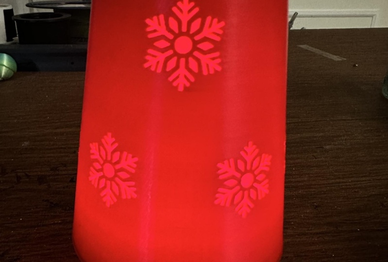
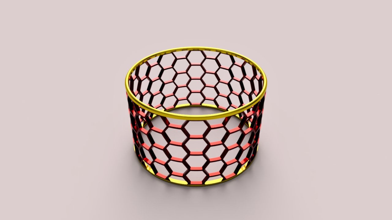
16. Emboss and Deboss in Autodesk Fusion: We are using the
emboss feature when we make a pattern
on our lampshade. It's important that you use the correct desired effect on your selected face for your
selected sketch profile. The emboss effect will raise the pattern from
the selected phase while the deboss effect will cut the pattern to
your selected depth. You can use the parameter you set up in the beginning
of the project. I called this parameter emboss since I had the emboss
pattern on my mind, but deboss would have been
a better name given that we used this feature
inside the emboss commando. As often, there's a bunch of settings that
you can explore. But we will leave the
alignment options as they are since we accomplish our design goals with our sketch and with
our construction plane. Once you zoom in, you see that
your pattern looks great. The idea is to make a thin 3D print
for the pattern. This will give your lampshade a
cool colored light.
17. Circular Feature Pattern in Autodesk Fusion: It's important that you select feature as object
type when you select your the debossed pattern. And a pro tip before you edit or play around with
complex patterns. Save your project before you
start advanced calculations. The need to do this obviously
depends on your project, your pattern complexity,
and your computer power. But this habit doesn't
really have a downside, so why not use the insurance. It can be a little tricky
to find the pattern. It's often a good idea to zoom in and look for that
bright selection. Your selection turns
blue once you select it, and all the snowflakes
turn blue since they are part of the same
circular sketch pattern. Once you select your axis, you're ready to set your
quantities and distribution. A full distribution means
that your pattern fills 360 degrees around your
axis. And that's it. We have a circular debossed pattern. Great job. Let's look at some timeline editing workflows in the next lesson. Thank you.
18. Edit Circular Pattern via the Timeline in Autodesk Fusion: Your actions are recorded
in the timeline, and you find editing options when you right click on
the selected action. The circular pattern is easily accessible in the
center of the pattern. Your deboss feature, which is recorded later
in the timeline, will update when you update your sketch pattern on
your sketch positioning. You can see how Autodesk
Fusion is recalculating emboss as soon as you
click finish skills.
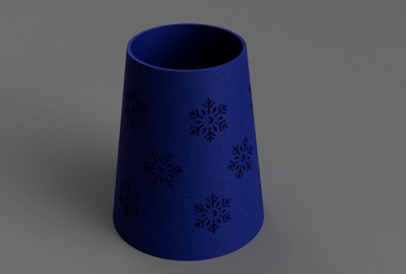
19. Add an appearance in Autodesk Fusion: Activate appearance with
keyboard shortcut A. You probably must make your menu larger if nothing
appears to happen. Search for your
appearance and just drag and drop it
onto your design. Did you know that
you can right click and edit the color,
roughness, reflectance, as well as accessing
advanced settings. I encourage you to
play around with different settings and
then I'll see you in the render environment
as soon as you're ready to render
your lampshade.
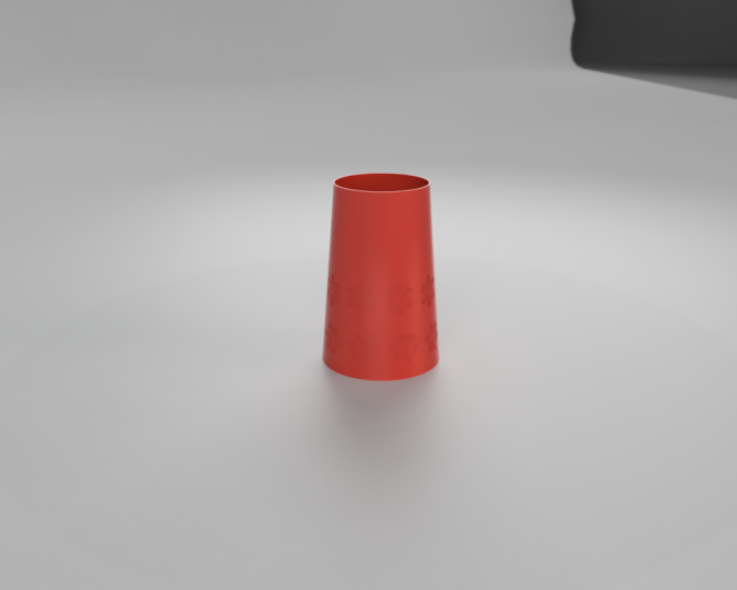
20. Cloud renderer in Autodesk Fusion: We'll make a fast and simple
rendering in this lesson. Switch to the render workspace
in the top left menu and right click somewhere in the canvas and select
scene settings. You can drag an environment from the environment library
onto your canvas, but remember to change the background setting
to environment. You can easily set an
image size. Pro tip here. If you're rendering
with the intention of putting your
image on a website, look up image size recommendations
from that website. You'll see the estimated
rendering queue time if you make a cloud renderer. Your project appears in the rendering gallery,
and once you're ready, you can choose to
download it with different settings and with or without a
transparent background. If you intend to place your
image on top of a photo, then it's obviously
convenient to download with a
transparent background, so you don't have to remove the background in your photo
editing software. And that's it for this
fast and simple rendering. See you the next lesson when
we export our STL file.
21. Export STL File from Autodesk Fusion: I just saved my project, so my latest information is included in the
STL file export. Remember to turn your
visibility off for any objects you have that
you don't want to export. Exporting STL files requires a cloud transition and
hence Internet connection. Your export can take a couple of minutes but
can also go faster. You're ready to take
your STL file into your slicer once your
export is ready.
22. Set up your 3D Print and Export G Code: I used the Prusa slicer
for this video, but the principles apply to any 3D
printing project. Importing my STL file
with imperial units, the second option, is
not relevant since I work with millimeters for my
3D printing project. Your object appears
on the slicer in the same direction
you 3D modeled it. Pro tip here; keep your folders
organized so you find your STL files without any distractions
or frustrations. We get data for our 3D printing settings
once we click slice now. This print will take 4
hours and 37 minutes, and we have data for the different parts
of the project in our top left corner. You can make a bunch
of advanced setups and utilize some basic
system presets. If we change to a layer
height of 0.2 millimeters, the quality preset, we see that our 3D printing time becomes
around 3 hours longer. It's up to you to find the
right balance between time, cost, risk, and quality. Import your G code into your 3d printer
and enjoy your work. We only have the
conclusion left. See you in the next lesson where we summarize the
project. Thank you.
23. Project Conclusion: Great job! You have made a
parametric lampshade with a debossed circular pattern. If you learned something new, please leave a review, follow my profile, or why not share the class
with your network? I hope we get to see your work uploaded in the
project resources. Thank you for taking
this class and see you soon on another
project. Thank you!
 Martin Lennernäs, Autodesk Fusion Enthusiast | Maker