Transcripts
1. SektchUp-AA Class2: Advanced Plugins Trailer: Hello and welcome
to training called Sketch up Advanced
Plug Ins, Class Two. The training will
be about one of the most popular free
modeling software title Advanced Plugins. Tell us that we will learn about advanced architecture solution together with organic shapes. If we talk about complex shapes, we need to mention about
additional plugins. The variety of plugins on
the market makes sketch up one of the most
powerful software to create any structure. The key here is to
know which plugin is used and it works in
different situations. With this in mind, this
course was actually created. I will show you free
plugins together with the paid ones that will be
useful in your daily work, not only to speed up
the modeling process, but also to create amazing
and complex shapes. You will learn how all of the plugins work
in the beginning. We will start with
the simple one, so it will be easier
to understand how to use any plug ins during
modeling process. Step by step, I will explain
to you why they are so important in normal
work and how they can improve the speed of
your modeling process. Then we will move to that one, where shapes are
quite complicated and require more work to do
without those plugins, More complex shapes will be
almost impossible to do. Of course, more advanced plugins mean more options and
more possibilities. But also a lot of knowledge is required to understand
how to use them. After completing this course, you will be able to design each building by yourself
from beginning to end, starting from
creating its concept to the final three de modeling. And remember, if you
publish any construction on your social media after
finishing this course, always at the
hashtag sketchup AA, it will be easier for all
of us to find your work.
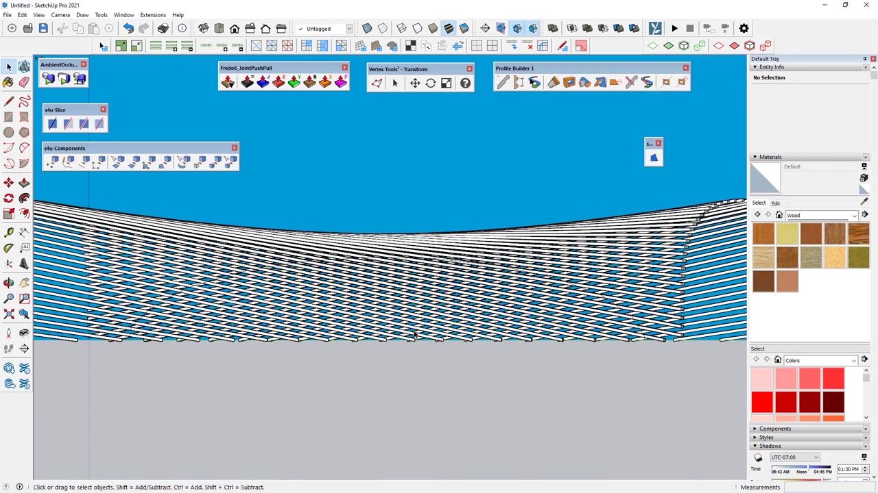
2. Profile Builder Introduction: The next also very useful
plug in for sketch up. The same important as joint
put pull is profile builder. Profile builder is extension
paid extension for sketch up that allows you to reduce
time to create profiles, for example, to your wire frame. Normally, if you
would like to add some profile or for example, you want to create some
assembly on a path, you will have to do it manually. On sketchup with the
profile builder, you can choose custom shapes. For example, models
you can copy, sweep it along, for example, path along some wire frame. This will increase
your speed time. You will be able
to mainly focus on your design and not
on your workflow. Personally, I use
the newest version of Profile Builder
with revision three. I always recommend to
update because developer always put a lot
of new features. As you can see, the To, there is a lot of icons, most of them are quite easy to understand through the builder. We need to start the
profile dialogue. As you can see, we
have the library with different type of shapes
for our profiles. We can save our settings for our modification if we done
something for this profile, or we can of course,
add our custom. There is also, as you
can see, red dot. It's meant that in
this place there will be the access
for this profile. Of course, we can change
it for example here or by hitting home on keyboard
during adding the profiles. The first thing that
you need to set at the beginning is the
dimension of your profile. We can change the
dimension in this box, and of course we have the aspect ratio lock and we can unlock it. It's means that we can change proportion after
adding some value. After adding the correct size, we can hit the built to add
our profile to the building. First we will select the
first point and the second. As you can see, the
profile is in the preview. This is the first stage. The next one, the
next, and the next. This is the way we can
build the profile. Of course, during the built, we can change the red point, for example, with the Home
button on the keyboard. And as you can
see, we can change the position after click Okay. All the profiles before
are also updated. We can add all the
profiles around our roof. At the end, we can automatically add the last
profile or for example, we can try to a sketch up
to do this by himself. Right now, I will just add the last one or I can
select close the path. And sketch automatically will close the loop with the profile. As you can see, there
is a lot of options. For example, we can apply
the material or the layer for which would like to
add the profile builder, it can be added to
the separated layer. Okay, this was quite
easy and fast way to add the profile. I will remove it now. I will start to draw the profile from the opposite direction. It's been from the
right to the left. The first, the first point, the second one, the next one. As you can see,
there is first issue that our profile is
inside the wall. The direction where you start draw profile
is quite important because sometimes you will need to have to put
the mirror options. For example, right
now you can see that profile is updated
and visible correctly. I will close the path. This is how you can
change the mirror for your profile and to put
it in the opposite direction. But there is also faster way to apply the profile and we
can do it with the path. First of all, I need to
create the roof surface. I will select it right now. It is in a group
with our building. I can copy it or I can cut it. After that, I need to exit from the group and
base in place. Now with the selected
surface I can hit, built a long path after that. You will notice that
in a very fast way, we already created the profile. I will hide the building. As you can see, it's work
almost great and very fast. This is the powerful of
the plugging that you can use different type of
path to add the profile. Of course, there as we move this profile
from the reference line, for example, I will
move it down from our top edges by
-500 millimeters. We can add minus or
plus. It depends. Now you can see that
we have the profile move down automatically
by this extension. Sometimes if you
have already created profiles and with wrong
direction in opposite direction, we can right click
on the profile. There is options from the profile builder to reverse selected in
a very fast way. You can also, from
the right click, make the mirror
for your profile. This was the basic for
creating the Profile Builder. In the following lessons, we'll discuss all
the rest settings.
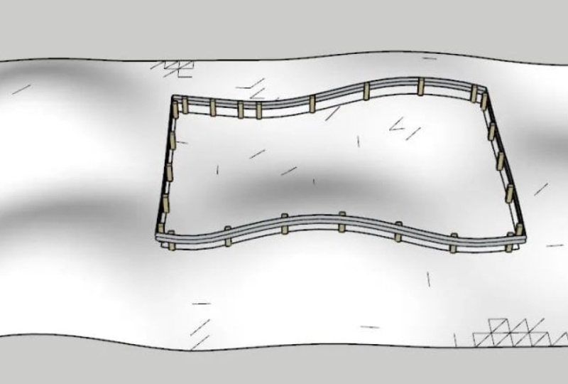
3. Profile Builder Along Path: Now we will focus more on creating reading
elements along the path. As you can see right now we
have some banded surface. It's not a flat, we have
some contour added. Right now I will try
to add some fence. First of all, I need to open the library Profile Builder
library with the assembly. Here we have some
models to choose. For example, I will select
the railing assembly 14. The first thing that we
need to do is to select the path and we can create
and build along the path. What you can see is
that our calculation, when it will be done, we will get the
railing on our path. This is the best that can be done with
the profile builder. What is everything is stick to the ground because our
curve is also lying on it. Now we will change the dimension for our
railing, for example, 500. What we need to do is to
change the attributes. On the preview
window, you will see the final looks for
our new railing. There is some changes with the selected our
present railing. We need to apply assembly
attributes by selecting it. And we need to wait some
time for the calculation. Now the sketch up, recalculate the results
Soon we'll get the preview. Everything is updated. We'll see that our model has been updated with the new look. This is, this is the
way you can change, for example, the dimension. But this is not everything
that we can do. For example, now I
will just remove, and I will not save
these changes. I will choose another wall, for example, this one. This time you will notice that the high
is probably too big, 3,600 And as you can see, after that, we have some issue. Because the model is
bigger than our path, I will change the dimension
to 1,000 I will also apply the attributes
with the results. There is still some issues. The thickness is probably
the problem here. But I will replace the
fence with under one. Probably we'll need to change
still high for this model. But I change it, for example, to crush barrier. And I will apply the attributes
and as a result we'll get really nice looking
fence on the path. This is the way you can do anything any models and apply it to your path
with Profile builder.
4. Profile Builder Library: In this part, I will explain
to you how to add profile to the library and how to
create your custom shape. First of all, we start with
creating some custom shape. It will be closed surface, something similar like this. Maybe I will add some
round on the corner. Next we need to
remove the rest of the uncut surface and
reverse the faces. Okay, this is our profile. We select them in
the profile builder, we click at and we need
to put some name here. Of course, we need to
set the center point, or at the beginning, how we will draw this profile. Later, I will set
the bottom left, because this will be my
axis zero or zero point. Then we can set dimension
and by hitting profile, we can add the profile. As you can see, it is
automatically connected, All the parts are together. Right now, I can change the size by adding
the next segments. All the profiles
will be rescale. I can also rotate it, or even I can make the mirror by clicking at
segments automatically, everything will be updated. By pressing Enter or Escape, You can accept your
present profile. There is a little
difference between the closed profile
and open ones. Now I will try to create some profiles only
with the line. Also very simple shapes. Okay, next line. This is how the
profiles, how it's look. Now first we need to create
smart path selection. Because we need to put the beginning and
end of the profile. As we can see, we have
different colors. The green is the
beginning, blue, middle one, and the
red is the end. The next profile will be orange, and at the end we
have the red one. It means that this is
the end of our profiles. We need to put some name, and of course we need to
select the correct points. The bottom left will be again. Okay, we have already defined
the profile with the built. We can start to
draw it as before. The profile is automatically
added to our scene. We can mirror it, rotate, change the scale, Everything that we only need by clicking Enter,
we can accept it. We can also select the profile right now and
reverse it if needed. There is also options to
create profile by path. For example, I will
select this rectangle and click Create Profile
with the path, we can also reverse it. First we need to remove the old one and again create the path. This is how we can add any
profiles to some lines. But there could
be situation that will have more complex profiles, more complex created
from different line. For example, I can select
all of them and we can add the profiles with
the quickest way of, as you can see in some parts is not what
we would like to get. For example, I would like
to select only some lines. First, we can try with
the smart path selection. To select the correct line, we will go to the smart
path selection tool. Now we can select by
double click on it. The line of course catch up
will select the easiest one. And we can build the
profiles also in this way. But I would like to
change the path. We will remove the profile by
selecting Smart Selection. First, I will select
the first line, the second one, the
next, the last one. Now we have selected
the correct path. Thanks to that, I can create the profiles along the path
that I selected before. This is also very easy and
quite easy to do right now. We can save the
profile and we will save it on our local disk. Every time we'd like to
load at this profile, we need to select
the first options, one is to save profile, the second is to load by
clicking the profile browser. We select the profile
from our list. Of course, we need
to know where is the default location
to save the profile. We can find it by going to
extension profile builder. And there is the preferences in the preferences
in the Pa window, there is the profile
library localization. And here we will always save
as default our profile. Okay, This is how we can create the custom profile and
add it to our library. As you could see, it's very
useful and very easy to do.
5. Profile Builder Edit: In this part, I'm going
to explain how to use added properties to change some parameters in already
predefined profile. The first option
is the material. In the material, we
can select what type of texture we would like to
apply to our profile builder. Of course, as you can see, we have some predefined
materials and they are in the select in the
materials in the model. You need to go up. In the model, we have
already some texture. Those texture came from the posture that we have at
the beginning of the sketch. Up when we start the program, I remove the material. As you can see, now we have clear window and the same in the material that is also
not listed. Anything. We need to go to the brick, we need to select the
material, add to the model. And then in the model, you'll notice that
we have material. And the same are listed in the material in
profile dialogue box. The same situation
is with the layer. It's work the same. Okay? Now I will
select some profile, for example, this one. I will select the material, the brick, and I will start
to build the profile. Okay? The first line, Second we close it. Okay? This is profile that
we have, and as you can see, it's a little small right now. We can change the attributes. It means I can
change the size in the profile dialogue,
for example, I will make it bigger
to 0.9 Right now, what I need to click to apply this dimension is select
Edit Member Properties. From the new window, I select what I would
like to change. As you can see, I can change the profile type rotation
from these options. X offset from here and the material junction
placement point of this red small point, Greco layer and extrude mode. This is what we can change
and modify right now. I will change the size. As you can see
it's profile name. I will select it
and as you can see, my dimension for the whole
profiles is changed. This is what we'd
like to get, okay? The first option to choose
is also the junction. The junction will give you some different type of
connection between each wall. The first options you can
see on the left side. Now we can select the middle
one when we close it. When I select the first one, you can see that all of
them are connected to one group in the
second junction. You can see that each wall
is in the separated group. Sometimes this could be
useful because right now we can each of them edit manual. The last one is the options were probably it
goes to the app. Yeah, this is a common problem. Always use the keyboard
arrow to draw the profile. It is the best options to
keep it in the horizontal. Okay, the last. Right now you can see that there is a different
type of connection between the walls
with some angle. It's just straight one. This is also quite useful. Now you can see that
also in the options we have each wall separated group, then we have the extruded
mode normal and follow me. Right now I will try to
select the follow me and I will draw the profile, the first wall, the
next one, the last one. Now as you can see, there is no connection
between each walls, and all of them are in
one group, as one solid. This is also very interesting and very useful for example, now I would like to
change the profile type, because in my opinion, it should be different. How we can do this, we need to change the
profile from the library, select the placement point, and with the member properties, we select the profile. After edit, you can see that our profile shape has been
updated very quickly. This is how you can
change any type of properties for the
profile builder.
6. Profile Builder Select, Trim, Hole: Okay, so this time
you can see that we have some lines and I would like to exchange all the lines and convert
them into the profile. First we need to select
the square profile, and I will select
all vertical lines. I will create the profile
built along path. As you can see, the profile
is too small for me. First I need to change
the value for dimension. Then I need to
select the profiles. I can do it automatically by select members,
by attributes. At this time, I can select all because all of them are similar. I will just click Select. I have selected
all the profiles. Now I can change the parameters, select parameters added, and now we have all the
profiles bigger. Now I will add some
profile on the top. I need to change it first. I will just select
all the lines from the top. Also. This one. We can now draw a
profile, a long path. As you can see, it's done. But now we need to trim
the vertical ones. I can do it with
the tools that I showed you in the
lessons before. First we select the bottom face. This is the first object, and the second one
is the vertical. Now I can select
each of them one by one to trim all of them. Okay? The next we will select also the difference
profile with rotation. I will select the line and
hit the build long path. Okay, now it's done. But as you can see,
we need to trim also this horizontal profile. If we try to use
the trim to fix, I select the first object
and the second one. As you can see, it's trim
but not in each place. Some still, we have uncut
elements in the bottom. This is why we need to use
function trim to solid. First, we need to
select the base object. Now the second one
which will be cut off. After that, you can see
that we have really nice cut off ends
for our profile. This is on both sides because
when I build the base one, I use all the lines at the same time and it's
treated as a one object. I don't need to repeat this function on
the opposite ends. This is how you can use trim to solid and trim Fai builder. Okay. This time I just
copy the profile to the right side and I will show
you how to add some hole. The hole you can use the whole tool and we have three different types
of whole circle, rectangle and custom shape. The first one is the circle, we need to put
diameter and we can add the hole to the profile. The second option is to
remove the hole very fast. We can do it because
it's place as a grope. The next example is
the rectangle we need to put dimension
and we can add the hole. Also we can remove it. We can also trim or
extend the profile. With this tool, you can see
that we have the section and our profile has been trimmed
and now we can extend it. And what is the most important? You can see that still we
have the hole in history. This is why it was
automatically added. Okay, the last example
is the custom shape. For example, I will start
to draw a shape rectangle and maybe some arc on the top. I will just remove
the middle line. I need to select
Hole, the shapes. Now we need to hit
Custom Shapes Profile. We need to edit. I will
put the name Temp. Temporary. Okay. Remember to click. Okay. Also in profile dialogue
you have selected. I can now remove the shape
and I can add the profile. As you can see, I can also remove it without any problems. This is how you
can add or remove different types of
hole to your profiles. There is also one quite
interesting function that sometimes could be very useful. For example, we can
hide the profile. To see only the path first, we need to select our profile
and there is the link with turn on the
profile visibility. Right now, you can see that
we have only the path and the section of the
profile. For example. We can use this view to the drawing, to
the documentation. We can hide all
selected profiles. And if we would like to revert the options
and turn on again, all the profiles we need
to select it and there is the second option to show
it in our workspace. I show you all the necessary and all the basic information and function about
the profile builder. Practice them as
much as you can, because we will use
the Profile Builder in the next lesson very often.
7. Place Shape and Zorro: The next. Very easy
without a lot of settings. Plugins, place shapes and Zero. The Place Shapes is rather
a tool board that allow you to add all the primary
shapes like sphere, for example, the hemisphere
tube and so on and so on. Okay, we can easily add sphere and rescale it with
the standard sketch up tool. Of course, as you know draw the sphere from the beginning. His sketchup is quite complicated
because we need to make a lot of operation
with the place shapes. You can do it only
with one click. The zoro slice tool is a tool
that allow you to slice. It means that you can add
section only with the mouse, as you know the sphere. It is also quite complicated because even with the pencil, it is impossible to draw on the surfaces without
standard tool. With the slice, you
can start to draw the line and cut something
with only one click. As you can see right now, we need to enter into the
group because outside the standard tool will
not work as it should. After that, when we
enter into the grope, you can see that
we can select one of the side and just remove
it without any problem. Of course, we can also add the slice on the
components on the grope, but to do this we need
to add the control. Of course, right now you can
see that we can add it with the standard mouse
bottom in the group, the same, we can do with few
shapes at the same time. But to do this we need to first
set the camera correctly. Something like this. And now
we are outside the group. We need to hit control. We can slice outside the group and all the shapes
that are in the line. You can see that now just slice both of
them at the same time. There is also one more options that we can slice anything. I will add the shapes. I will use the standard section. We need to enter
the grope and we select the sections
section plane. Maybe I will move it inside. Right now you can
see that right leak, we have mode at selection. After that, if I will only
remove the section plane, you will notice that we have the slice the same
as z with the zoro. There is also one quite
interesting options that we heat the control. We can also set the
line horizontal. This is also quite useful. This line will snap,
as we can see, both very interesting plugging and sometimes could
be very useful, especially at the
beginning when we need to add some standard shapes.
8. QuadFace tool: The next very useful plugin
is squat phase tool. It's a free plugin, mostly used in architecture, for building, for
all modification. If we want to create, for example, some
organic shapes. Here we have the
sphere, for example. If you would like
to see a geometry, we need to select hidden
geometry or remove it. This is what we need
for all the time. With the quad phase tool, we can do it faster by
click on the select. Then we see Hole the grid for our sphere or for our solid. The first option is to
select the surface. For example, we can select the surface and we would like
to increase the selection. We would like to also select additional surfaces that are connected with our first one. There is the options which
is growth selection. By click on it, we can increase the selection from
our base surface. For example, after that with the joint push pull,
we can, for example, make some X route selected
for all the selection. There is also options where we can decrease
the selection. For example, decided
that we'd like to choose the smaller number of the faces. There is also option to
select the edges individual. For example, we can select all the horizontal or vertical
line at the same time. Very useful if you would like
to only select few of them. We can increase and
decrease the selection. It's very similar, for example, to Free Studio Max
if you use it. For example, for the edit poly. There is also the same
method with the loops. We can increase the
selection for the loops. For the vertical
and horizontal one, we can increase and
decrease the selection. Sometimes there will be
necessary, for example, to divide some square
with more edges. For example, we can
do it by selecting all the sphere and
turn on all the quad. There is options for
dividing or elements. By selecting, again,
you can see that we have additional divided line. We can, for example, flip it if needed with
the first options. There is also options
to height all of lines by selecting
deferred options. For example, if you need
more edges for modification, it is the best way and the fastest way to
add it to your solid. The next options is, for example, more
work on the surface. For example, we can select the edges which is added and we can convert
it into the quartz. Thanks to that, all of the edges are connected from corners, and this is how the
correct quote is built. For example, the same
here we have two lines, but they are not
connected on both ends. We can try to build it in a correct way by adding
the lines on both sides. And now as you can see, each edges is connected with one point and with each corner. This is how the correct
quot also build. This function can
fix some issue with wrong built surface and it is possible to
convert it into the qua. The same situation
is if you would like to convert any
mesh into the quats. For example, here we have two surfaces with
the edges between, we can convert this
mesh into the quats. For example, I will
just select lines. We have two surface
divided lines and we can remove this line. By converting it
into the quartz. And now you can see that we have one surface
catch up to treat it as one surface without
any divided lines. The next option
is possibility to create quotes from
the wire frame. So as you can see, I have
the simple wire frame from the edges only
with the pencil. And now I can convert
them and build the qua, surface between the edges. So as you can see, there is some calculation and sketch up, we'll calculate the surface
for our wire frame. And now we have applied, sometimes there
could be a problem with different type of plugins. They are not compatible
with the quad phase. For example, the sandbox
is one of the plug in. For example, if I will build the surface from the scratch, I would like, for example, to select some edge and make a grow or
something like this. It is impossible. What we can do is to first select the
surface from the sandbox, and we need to convert it into the quartz with
the Quaal options. After that, we can again
work with the surface. For example, we can
select the edge and we can grow the selection. For example, you can see, now everything work perfect. Sometimes if there is some
problem with some elements, always try to convert it
into the quotes, okay? The next one is convert
blender to quad phase. For example, if you use blender, you can import those model and try to convert
it into the quotes. The next options that we have here is working with
the UV mapping. You don't need any
additional plug ins because quals has UV mapping. First we need to select and add any texture
into the model. To do this first
we need to go to the texture right click
on it and add to model. After that we need to
select this texture. We can turn on the UV mapping. First we need to select
the first point, then we need to select the U
direction and the direction. As you can see right now
with this small cube, I can change and rescale the texture to get the
proper dimension for it. There is also options to fast copy and paste
mapping to another shapes. For example, first we
need to select the point, the one direction and the
second direction we have copied the texture and
after that we can paste it. We also need to select first
point and both direction. There is also option to
make warp You mapping, to put it on the planar surface. To do this first
we need to select also the points, both
direction, okay? So this is the point, the first direction
and second one. And then you can see that texture has been
automatically copied. And we have the surface from the bend area and from the
blunder at the bottom, you can do it just in the T. There is also options
to make more smooth, any elements we'll
turn on the grit. There is options to make the smooth quatre
smoother shape. We can also shape it, we can make it smooth again with the sharp edges or the edges will be the sharp
and we can select it. Sometimes it could be useful if you would like to
make some modification, because as you know with
the smooth elements, there is always problem
with some modifications. We can add some
loops, for example. First, we need to select the
edge and we can add more. More loops, more
loops, of course, more smooth for our solid. But it will be also problematic, especially if we
have a lot of loops, a lot of edges. We can also remove the edges. So as you can see, it will also modify the shape and it will be more
sharp because we have, of course, less
edges to connect and to build the smooth
surface between them. There is also options to
draw the line in the middle. For example, when
we hit the control, we will add more divided
lines on our surface, it will be very
useful, for example, to divide the quotes with
the shift on the keyboards, we will remove the
additional lines. There is also a pencil because sometimes there could
be some issues, something can go wrong. For example, as
you can see here, we have two surface but sketch
up will show is only one. With the pencil, we can divide the surface as you can see. Now it's fixed. We can reverse the
faces and we have the correct built quotes. The last options is
some analyzing to show, for example, which surface
is correctly as a qui. For example here with the red, this is something wrong
with this surface. The blue is accepted
but also should be fix, For example, to fix the red one, we need to add additional lines to connect all the
points together. As you can see, still
we need one edges here, so we'll try to divide it. Now we need to add more of them to remove all the
unnecessary colors and to have everything green. This is how you can
build a quartz in a correct way to remove all
the unnecessary colors, especially if the red one
should be eliminated. Because this could be
problematic in future, especially if you would like to port your model to
other software. If we talk about the
quote phase tool, all those first options are very useful and we will also use
it during the next curses. Sometimes very useful is
also to add the loops or remove loops is
not recommended, but to add more lops for more modification
is always welcome. Try to practice all of
these options because we'll use it a lot
in the next lessons.
9. Plugin FFD: For more complex
shape modification. There is also the plugin
which is called FD. As you can see right now I
have the box for modification. I can write click
select FD Plug in from the popup window and we'll start with two by two as you can see. Additionally, we have
some black points that can be used
for more control. Right now, it will be quite
hard to select those points. Sometimes it will be almost
impossible by moving it. You'll see that we still
move the whole grope. But in the outliner there
is FD control points. By selecting it, we
can change the name or select all the points. For example, right now
I will select four but maybe two front top. We can use move rotate scale
to make some modification. This is quite easy to do, especially if we have
only few points. We can also rotate it, we can also scale it. This calculation for
sketchup is quite fast. With higher number of patch, there will be some time
for calculation right now. We will try to use free by free. So as you can see, we have
free section, unfortunately, when you select those points in the middle and you would like to make
some modification, you will notice that
nothing will happen. This is because we need to divide this box
to more phases. I will just go back and I will remove all these
D control points. Now I will select the next options which
is called n by n, F D. It's mean that we set
the value by ourselves. Again, free subdivide face. Right now as you can see we have the same
situation as before. We still can't use those
points in the middle. This is because we need to
divide those phases also in F, in FFD, end by end, we need to select
subdivided from force, which is default
to true options. Thanks to that, our box is
now divided, as you can see. We can select each of
the phase individually. And also, if we will move the control points
from the middle, now they will start to work. You see, you can add this modification to create
really amazing shapes. Okay, let's just go
back to end by end. For example, we said
10.10 As you can see, we need to wait for
adding the faces. We have a lot of faces. Of course, with a lot of faces we have a lot
of control points. This modification sometimes
will be more problematic of the results will be some
gaps or with some issue. For example, here you can see on the left side that we have some gaps because we
modify this box too much. Okay, Now the next example
I have some tubes. The group, I have added
FD control points. And now I will
select some edges, for example this one. But maybe before that
I will select that also some colors for
better visualization. Maybe the red one.
Okay, I will select those edges from the bottom on the red color and
I will lock them. Right click F D lock
edges right now, I will try to use FD control points to
make some modification. Again, I will select those
elements once again, double click for example. We will try to rescale it with the control to have the
scale in both direction. Now we need to waiting
for the forming. As you can see, we
have some deformation, but our selected edges Ds, which were locked, are
still in the same position. This is how the lock work. You can freeze edges, they will always stay
in the same position. Of course, right now
I select just once, but we can lock more of them. There is also a possibility
to create the patch, but first we need
to select the axis. If you will right
click somewhere in the workspace in Sketch
up, this will, won't work. We need to select
one of the axis. Then you will get
the options for FFD. With the FFD, we
select make patch, for example, we can
set 55100 by 100. And we select, okay, now we have some patch
plane already with the control points and we can use them to make some deforming. This is how the FFD work. Always remember to save you work before starting to modify with
the FFD because sometimes, especially if the
model is very complex, sketch up can crash. This was FFD plugging
in sketch up.
10. Curic Align View: The next plug in Uric view. This is some of this plugin that will help you
with your workflow. It is not connected with any of actions like modeling
or creating the shapes. Mostly as you could see, we have to switch between parallel projection
and perspective. We always need to go to the camera selecting sometimes
this could be annoying. This is why we can use
icons to fast switches. Can see first we need
to rotate camera. After that when we hit a line view sketch up,
automatically rotate it. This is very useful and you don't need to go
to the camera and select from the sub menu
by double click on it. We also switch between
parallel and perspective. This is one for me for the coolest feature because I very often switch
between those camera. We can also lock the view. Right now, we cannot rotate it. Even the camera is lock. We can still do any
action as normal. Right now, we can just
back to normal camera. We've unlocked by double
click on the icon. What we can do more, we can align the view to
the selected face or edge. For example, I will
select the pace and I will make the camera
apparel to selected phase. Or we can also select
the edges and make camera perpendicular
to selected edges. This is also interesting. You can also choose
camera, for example, by easier modification
from some site. There is also a possibility
to set point of view. Point of view only work
in perspective mode. You can increase the
perspective or reduce, it depends what you need. I always recommend
to always back to the default value
which is 45 degree. We can also change the point of view in the sketch up here
with field of view. Here we add some degree in sketch field of view
in other software, this is point of
view, it depends. The last and also quite
interesting function is that we can add shortcut. For example, to change between
perspective and par in the sketch preferences
we need to search for al view current. We can assign some keyboard
letter, for example, for me now I can, with the keyboard, switch
between perspective. For me, this is something as a must because I switch
between them very often. And right now I can do it
faster only with the keyboard. I recommend to use this
plugin and install it.
11. Plugin s4u components: The next plug in for components. This is mostly very
useful plug in, especially if you want to work
a lot with the components. Create components,
replace components, add some components to
existing wire frame. Normally, it will spend a lot
of time to do it manually. Components, it will be only
few clicks with your mouse. Okay, so we will start with the first
options, 0.2 components. This means that we need to add the construction
points to sketch up. Unfortunately, in sketch up
with the standard tool bar, it is impossible to
create the normal points. It's really frustrated. But you need to use
additional to add it. As you can see, I have to draw some points with the Point
tool plugin that you can download from the
sketch up warehouse and we'll draw some
construction points. As you can see, I have
five points right now. I will add some shape, some solids, some very easy one. I will convert it
into the components. Right now, I will select the components together
with all the points that we have in the workspace. Now, I would like to
add these components to each point on our workspace. As you can see, in a few
clicks and in a very fast way, I duplicate each element, and even I will make
some modification. All the rest model solids will be also
automatically updated. Okay, The next options is the
draw lines. Two components. First we need to
select the components. This is the windows pop up
that remind you about this. We select the components and we can now start to
draw a normal line. But instead of line, we have the components. We can put them in
different direction, of course, until we hit
backspace or escape, we can still draw it. Okay, the next one here we have two different options to set our components and
convert it into the line. We sell a components line, as you can see in a few clicks, we have components
added to our path. Of course, the most
important is how you set the axis for
your components. Right now, the blue one must be direct the same direction as our components, as our arrow. Then this will be
possible to add it in a way that you
see on the screen. There is second options with the orange works very similar, but the results
will be different. As you can see, the arrow we have in a
different direction. It depends what you need. You have always some options to choose with
different solution. Now we can also copy our components into
some banded surface. As you can see, I
have the surface, I need to explode to select
only surface individual. And I need to select
Components and copy now by clicking
with the mouse, because as you can see we
have still the blue arrow, I can change the direction
for the components. I can also select
from the right click some additional options to set all of them at the
same position. For example, What is more? I can, for example,
change the shapes. I will open the grope. I will make some modification, for example, to add
some glass material. Now we can select the material with glass
and we can edit it. And as you can see,
each component will be also updated. This is Very cool feature. Okay, now the next comment
that we have here, I will edit the components. You always need to remember to put in a correct way the axis. Okay, the next examples, we have three options. Phase two components. First I will select the
phase and select components. First, we need to
create the group. I will just put middle
points here with the green axis
directed as our cross. And now I can
select the path and components and we can
phase two components. Now as you can see, I need to, with our blue arrow, set the correct options
and if it will be done, I can set the finish and
we have the results. It's look quite nice. Okay. The second options work in a similar way but give
you a different results. And the results will be
with the common repeats. As you can see,
our shape has been repeats in the same
way for each element. Then we have also the
path and the objects, and we will select the
phase two components range. As you can see, the
result is quite nice. But in the middle we have different objects
with some angle. This time we can use
the uniform solution. As you can see, we have the
correct each the elements. Also, as you can see, sometimes
it is worth to choose two different variations to different options to
see different results. Then we have the shapes and we can copy it to our surface, even if surface is bended. As you can see, this is
the results right now. By click with the blue arrow, I can change the
rotation for our object. We have the free last options. This is mostly used to convert, for example, group
into the components. Right now you can see we
have different group, they are not components
because you can see there is no auto update
for modification. Now I will select all of them and I will select
group two components. Right now, they are converted
into the components. And by selecting
one and modify it, you can see that all of
them are also auto update, the same situation, let me say solid components
or object to components. Right now we have already
predefined components, but they are not the clones, which means that each
of them are separately. Right now the last one, as you can see, is components. So we'll create it now. I will select all of them and I will convert object
to components. Right now you'll notice that we can work with them as
the normal components. We can modify one and all of
them will be also updated. Very useful function. There is also possibility
to replace the shapes. First of all, I need to select all the elements that
need to be replaced. After that, we
select the icon and we select the correct shapes. In one click, we have
updated elements. Of course, again, always we need to remember
about the axis, how it is, how it looks, orientation of each
axis in each component. This is how you components work. I really advise to use it because it will speed up
your work really a lot.
 Filip Design