Transcripts
1. Introduction: Hello and welcome. My name is Brian. This class I'm going
to walk you through PCB t signing in orthotics ego. With my two years experience, is an electronics engineer. I'm quite confident
that in this class we have definitely going
to learn something new. In electronic
engineering enthusiasts. Just say what beast in
this class is for you. In the class we're
going to lay in various concepts ranging from
block diagrams, sketching, transfer in this block diagrams into PCP schematics and ego, inverted as laboratories
in ego because sometimes you want to
achieve something, but then you can look through library and the
library is not there. So I'm going to show you how we can add these various
libraries in ego. From there we'll go on to do board layout and doing
step by minorities. And I'll also show you how
to draw automatic routing. From there, then proceeds through finding out how can
I get my board printed out. It was this are things that
are done for real projects. Drilling wants to come up
with something. At the end. You will notice that
this course will be hence on throughout, went to be working one
sample electronics project. For the prerequisites,
what you only need, just the laptop way you
can install this software. And most importantly, your
desire to learn something new. At the end of the course, the final projects which will squint to be
on board dinner. No automatic change
of a switch in this two is going to
follow the same procedure. Is start with designing or
drawing new flow diagram. Do we know PCB schematic, your board layout
in drought gene, then they give a
file for printing. I'm just going to show you a simple projects if sample personal project
that I've been working on to just show you how this
thematic look like and also how the board looks like. Before we get started. This is a schematic. This is just a simple schematic from a personal project
that I've been working on. And you can switch to boards. This is the port F just
done some routes in on it. From the EA. What's left is to just finalize
the board layout. Then January the gap of. In the next video,
I'm going to show you how to download and install the software and just grant through the basic interface
of this software. Before we get started.
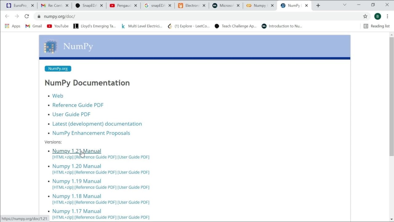
2. Eagle setup: Hello and welcome
to today's class. I'm going to run you through the installation process of ego, the Autodesk ego, what
you drew in your process. So you can see I'm in
my Chrome browser, you come in type
Autodesk Download. Once you eat in day two, outputs lots of search results. You will look for the one by orthotics that this
the official website. As you can see, the
NHS click on it. It will take you to a page
way you can download. Few things that you
need to specify is the operating system
that you're running. So for me, I'm on Windows, on Mac and click on Mac. If you're on Linux,
click on Linux. I'm going to download
for Windows. If I click on Download, it should start the
download in a few seconds. Okay, so as you can see, it started downloading and it's just a small file which
is around 125 MB. So I have already downloaded it, so I'm just going to pause it. Go to the downloads folder. In the downloads
folder, you can see it. The 80s orthotics ego 9.6.2, they fish in 64 beat. I'm just going to
double-click on it. Then just click on Yes. The initial just
accept the agreement. Then they choose the folder
that you want to install it. For me. I've already installed
the ego in my machine. Already exists. So I'm not
going to re-install it again. But what I'm going to
basically show is that after I've installed it, it would probably create a
shortcut on your desktop, which we can click to
launch the software. So for me I've been
Teton, my text box, I'm just going to
open its opening. It's already open. Okay, So this is basically
the interface of the ego. Software. From the AI can see
there are libraries, design blogs descend Ruth's
use their language program. And all these ones mentioned
the libraries that rule. Later on in the course, the class we are going to talk about how to load libraries. Not everything that
comes with ego. Some of the libraries we have
to import them yourself. Once you start off, we want to instead
with this schematic. That's what we'll
be starting with. Click on File. Then you go to
what we want to do is to create a project which we are going to name after the costs that we
are currently working on. So once we create a project, so a project is basically
sort of like a folder, but then it has a
specific maybe objective. Maybe this is the project to design an automatic
change of a switch. So it's more specific. Then within that project, you can now create
your schematics. So now we can see that
there's a project's aorta df, another project which is Ca. And then this is the new project
that we've just created. You can choose to rename it. So in this case, I'm going to just name it PCB. Let me name it PCB class. This is the name of the protests
that have just created. If m2 right-click on it, you can close the project
and then now go to New. Went to start with STEMI ticks are going to click
once thematic. But again, sources in
that there is board, there is lab writing library. That's way if you want to actually generate
your own library. But for us, we just want
to use this gamma thick. And it also utilize the board for the
library just going to import libraries which are
already made or impulse, then click on this schematic. If I click on schematic, each output,
something like this. Where we are going
to be doing most of our staff before we
move on to the board. I just wanted to print out through a little
bit of functionality. Third tree F in this schematic. This is one of the most important aspect
where you can add there, but if you click on it, it should take you way. We have like fatty paths,
fatty acid libraries. You can create. Maybe you want the arbitrary
you can click on neat. Then need to show you various
symbols which you can pick. And once you click on OK
to go into your schematic, that's one of the things
that we also have. The more Jew loosely if
the nits when you want to actually make
the connections. We also have this one, the nail. You can actually
rename the components. You can place values on. Maybe I say if he
resists that you want to put the value
to the resistor, you can use the value
of them's called P. The pests they delete
can always explore these. Okay, so as you can see at
the top here with this one, we are already used tweet. We know that's
where we can save. Again, do anything there. If L di dt with drawing
a few, IF true. So also utilize this to stay up a lot when we are now
doing the board also, they're, they're out in delivering the
spacing and all that. Then from the library, that's where you can upload all import a specific
library that you want. And that's basically
the interface of our equals software. We'll come back to
this after the next, the next video where
we are going to be talking about the
block diagrams are going to draw them a specific software that we can use to draw the block diagrams. Then we'll draw
the block diagram that we're going to be
using in this course. And then from there we'll
come back to this schematic to actually implement
the block diagram. In the next class,
we'll also discuss the actual topic that went
to be working with posts. I mentioned that this
is going to be hence on focusing on a specific
electronics projects. Discuss more details about the projects in the next video.
3. Sample Project + Block diagram: Hello and welcome to yet another class and interesting
one where we are going to discuss about the
project that we're working on and then move on
to the blob data. And for the project. What we're going to
do in this class, we went through developing
a to deploy ATA. What we're going to
do going through, I drew a PCB or feets and
print it out to deep. Plata is basically uploaded that offers the fastest way and efficient way of producing
a fairly large drawings. We are engineering minded, so we want to come up with things that solve
our day to day life. So that's why the introduction
of the true deep low-tar. So that goes very like drawings. You can easily do them using these two deep rotor biscuit
principle of the G code. So G-code is the most widely used
computer numerical control, and that is the CNC
programming language. Using CMC, we can control the two, deploy ATA through
certain microcontroller. So in other words, we can say the two deploy
ATA is in embedded systems, so it is a microcontroller. We feed in the G
chord to control it. And then from there we can
send signals to control. So in this case we are going
to do it to deploy it, again, control the x-axis. We can control the y-axis to draw whatever the
drawing that we want. Okay, So now that we know we have an overflow
or 41 to work on, Let's now start
the block diagram. You can see this is an online platform
where you can do your blog diagrams
in your browser. You can just type, press Enter. So I'm just going to
click on new diagram. This is our first item. I want to create
a block diagram, so I'm going to maybe
let me just name it. You can give it an anomaly. For me, I'm going
to call it florida. Be underscore block
block diagram. This is what I'm
going to name it and then I'm just going
to click on blog, dag, blink, dare
Graham, then create. Want to say FETS, let me just say to d. Now click on Save. And then it opens this. From here we can draw
the block diagram. Blown diagram yes or no is basically some rectangle ships. But they have to be connected
to show that the general, just like some shapes
like rectangles, which, but these have to
be generally connected. That again, see sort of like your workflow of
information in our system. We're always starting
way, are we going? And how things connected
within the system? Let me say, let me say this. These are the rectangles, right? Let me just enlarge it. Rotate it. You can start from here. We already mentioned that this is going to be
an embedded system, which microcontroller
we're going to be using. It's a good question to ask. I'm not really going
to go deeper into maybe choosing a specific
microcontroller. But you need to come up
maybe with the Pew chat, which is going to compare
various microcontrollers. And then based on
the architecture and watch you renew
and drew with it, you can come up with one
that works best for you. For this, we are
going to be used in ATmega three to eight. That's the one that we
are going to work with. This. This is the central
part of everything. Is going to like this is the intelligence of
the system was from the microcontroller within code to perform various functions. I'm just going to
double-click and then I can type at omega. Now that we have a
microcontroller, things that we know is
that this is going to be an embedded system
and this going to be sort of like a
stand-alone system. Another system. But then it needs its
own power with our eye, we are going to power this because we know that
the microcontroller, as they work with
very small voltages, so we cannot power it from the simple that is supplying
maybe the deepest system. Now we are not really weren't what kind of supply
we are going to use. The noise that we will
need a power supply. So I'm just going
to see this play. How is it going to be related
to the microcontroller? Is going to be Feagin
metric microcontroller. So you see the
arrow it limiters. So now that we have the
power supply, I mentioned, we really need to
figure out how is it related to the microcontroller. So you can see that
as I've mentioned, that these
microcontrollers work with this setting specific voltage. This is the job of
the power supply to supply that acceptable
footage range, current range for
the microcontroller. So you see the arrow
is pointing into the ATmega three to eight. Once mentioned previously that this will be controlled
by CNC or the G code. So we need to indicate that
as well on the block diagram. I'm just going to put
here double-click. I'm just going to say G code. This one is also going into, going into the the MCU. Now we are done with the power supply and
the cheek quotes. So these are the main
things that we need to be able to utilize
this microcontroller. What's next is twice
Ollie Green to do with the information. And the power that
brings apply to this was you cannot just supply power to something
which is I do. This is to contrast something. So it's going to control
some motor drives, which will then drive
the 2D plotter. Since we have a 2D plotter, We are basically going to
live through motor drives, which are going to
drive the system. Then these are going to be controlled by our, these are going to be controlled by our, our microcontroller. Now we have this div address, the extra one for the
x-axis and the y-axis. So moving on. Now if mortar, which is going to be
controlled by the driver, both for the x and the y-axis. Since this going to be
controlled by the driver. So you have an arrow going to the motors and go
into the mortar. This girl, this is how we are
going to design the system. And basically the flow diagram of how it's going to be working. So few things to discuss. Which kind of stepper drive, how we are going to be using. And probably some
justification on why you want to use
that for this class, we'll be using the A4 988. This is discarded because
it's so porous in bipolar stepper motors that
is in full, half, quarter. Thanks Christine, step months, which is a good
quality or attribute. It also essay draft
capacity of up-to-date Fe falls and plus
or minus two M's. Disregarded. This is
the block diagram. And if you have
any other question that you want to design
a block diagram for, you'd really want
to consider what needs to go into the system. Consider that it is
an embedded system. Standard law, and it has
some intelligence in it. It needs a microcontroller. What goes into the
microcontroller so that we can be able to
control the system. Okay, Now, what's going
into the microcontroller? How is it going to
control the system? The systems,
basically the motors, which are part of
the main hardware. But what's controlling
the motor? Stepper driver, which
is basically controlled by the the microcontroller. And also really take note
of the power supply. You cannot power the MCU from the main power supply
of the whole system. You can bend the MCU because it is its own
power requirements. You need to consider that. In this case, we have to think of what are we going to
use for the power supply? You can use the voltage
regulators or the HAL CAPM. Sarah three is also
another module that works well when it comes to
stepping down the power. The allowable range for
the microcontrollers. In the next class,
we are now looking into the main schematic. How are we going to translate this block diagram
into a PCB schematic? And then from there, we
implement this system. See in the next class.
4. PCB schematic - Adding Libraries: Hello, Welcome to
your tenant class, where we are going
to now begin talking more in detail about
the PCB schematics. You can see this is
this green that we created in our setup. Indio. Now we want to blow
out through photos libraries that will be useful
for us as we start the schematic for our project. There is always one
important library that you need to import
before everything else. So I'm just going to move
into my Chrome browser. And libraries called the DIY. I just said DIY equal
library downloads. And then Enter. You'll see stitched
result from Autodesk. Need to click on that one. When you scroll down,
you'll see DIY. And once they see that
one, click on Download. Then new to start
downloading for you. It's done downloading. You are going to move back to
our schematic. When we are. We want to see how we can import this new library
into each group. At the top, you can see
my case, that is library. So you keep on lane road. Then click on Open
Library Manager. Once you click that,
it'll just take some. Again. In this case, it didn't take
in terms you might find that it will take
some time to login. I'm just sitting
up or refreshing the LED brightness that
now you can go to in use. So you want to look at the libraries that
are currently news. These are the libraries
that are in use. But L1 through it,
the DIY module. What I do is click on Browse. Once I click on Browse, I should specify where the downloaded
library went through. So for me, in 20
to my downloads, there is one problem. I didn't extracts the zip
folder for mainland bright. Let's go and extract and
then we see how it goes. This is the one I'm just
going to I'm just going to right-click on it and
then extract the TA. So always remember to extract because if
you don't extract, it will not be read. So let me open it. Extract to some extent in it to my namely extracted
two main documents. Maybe just cross-check if
there is a lot of fail see. But you can see TA, this is the extracted DNA. Why images? You can see also,
It's an ego library. Now you can move
back through our ego speaks equilibria ad manager. Then click on Browse from
going into the documents, both that sway, stretched it. Then C, T, and then you click
on it and click on Open. Once you're done with that, automatically edit to the
libraries that are now in use. So to just confirm, we are going to
scroll down and see. Okay, so you can see is now we can close the library manager and
go back to the schematic. Now we are in this schematic. But remember, we want to utilize the A4 988 stepper
motor Dry Farm to see is it that we can
have it available for use? And remember in the equal setup, I mentioned this,
this butter on it, but you have to
click on this one. Once it click on this one, it will take you
to all the paths that in various
libraries in your IPO. But before we actually do that, we would want to add title. Skim active. As you can
see, it's just blink. We would want to just
some titled to it. So what you do is
to type, frame. But read TO don't teach you one a skill or technique
that you need to use. As you can see all these paths, they're written
in specific name. So you can see 75th one. Let's say you do not really know the specific
name of the part. You will use the asterix. This one, once we put it to
look through all the paths, for one that is a similarity. You just note that there
is a frame in the name. You can just put framing the
aesthetics and then you eat into so the two stage for
everything that is frame. You can see we have frames, etcetera, only a library
that we just four frames. And we want an A4. So we have an A4 sheet or
with our schematic or fit. So once you click on this
one is much better for me with the title at the
bottom right corner. Once you find the frame that
you Andy just click on. Okay. Then need to take cubic
to the the design manager. Then in the design
manager would want to align it with this. So you can see there
is a plus sign off. I suggest Laney to
descend the plus sign. Okay. But when we click Okay, you will notice that
this frame doesn't call, do is just press Escape to call. This come back key
so you can see that it is filled all my screen. But what you can do is tune. Assume each two
feet, this green. Zoom to fit. Then you can see this is
my frame and disease, the title PCB class
and is not saved. You might be wondering where
did the PCB class came from. So it'll automatically
tick the name of the file. So you can see that my schematic to PCB
and the scope class, that's why it peaked PCB
underscore class as the title, this schematic in
DA to be updating you where the saved
or not, the document. Now we have these tightrope. What do you want
to do is to go big to remember you wanted to
look for the stepper driver. And we know that we
are us in the 988. This eat enter and see
if we can find it. Here. You can see that saying,
Sorry, no, Mitch. In other ways we do not
hear the librarian. Let here's the A4, 988. What do we drew? We
have to go back online, search for the library, Corbett to the library manager and Dean portraits as well. I'm going to go back to my
Chrome again in microbiome, there is this website. I usually find most of the
most of the libraries. You can type snap, EDA. Eda can just call. It has lots of A free libraries. All paths that we can use. In our dry 14988. Click on search paths. You can see 4988
motor drive fast. So what I want to do
is to go on and say download models and from AAA
to show you the footprint. The same goofy Texas. So unfortunately the 2D model for this purchase not available. But this is the footprint. You can go onto. Each download. Footprint. Make sure that
you download for ego. And it's done downloading. I can go a bit to my schematic. In the schematic
I did echo again to library, pen library manager. In library manager unquote
through the night browse for the downloaded library. Into my Downloads. This is the one I click on it, then click on Open. So it is edit. Once you can see there, the morpheme on the
edge means it is edit. Now I click again on part. We have clicked on
the edge bitrate, so we are here, the
tape again, a 4988. And you can see that
it now appears here. Microstrip interest, valid translator and
over-current protection. Then once it click on
or K to take you here, and you can just click
on the, on the surface. Remember we need two
of these since we, since we are having
it to d plotted. So we need two of them. So I just want to move them. If you want to move them, you just click the More. And then you come
in, click here. There's always some plus
saying on the patch. And then you become
click and drag. In the next class we are going to now move forward from here. Making the necessary connections
completes this gamma G. See you in the next class.
5. Motor connection to Stepper Drivers: Hello and welcome
to today's class. We're just going to continue
from where we left off. First to get started, I'm just going to recap what
we did in the last class. We created our
schematic and remember, we created the title
for a schematic. For this course, we have
PCB class is our schematic. Yes, So today I'm just going to go apart into our schematic. Going to the, going to add the motor stepper drive
into a schematic. Remember mentioning that
in a case that you do not know the exit of the parts, the two and to use the outcomes. I'm just going to say for nine was a naught that
in the name there should be some a 4928. Once I'm done with the A4, 99 feet and in due to loop through all
that is the A4 nine, then you just select the one that corresponds with a21, a22. So I'm going to
click on this one. And then I put it
into my schematic. Remember we mentioned that
from our blog diagram. We saw that we needed to motor drive as to
drive our two motors. That's why I input to motor stepper drivers
into my schematic. The size is a bit small, so I'm just going to zoom it in so that we can clearly
see what's there. These are the motors
that we have. Now. The stepper drivers
in our schema t. Once the next is to figure
out how the motor is going to be
connected to these. Once I figured that one out, we can know what's next. What is it that we need to do? What we know is that our
motor is going to be connected to the A2, B1, a 1-p. that's
the first term. The second motor is going
to be correlated to one. The sequence motor is going
to be quantitated at 11 b. How do we make those
connections to external motors? Use the pin head from the *****, then we can now screw in the
y-s going to our more time. That means we need
another part in our schematic that would allow
for that connection. That is some pin here. Does AI to do is to, what do you do is
to coat back to it. But now what we
want is a pin here. I know that in the name
there is something I pin, pin, pin. There should be
something like that. The name. Alternatively, you can just
look for the light branding that contains the opinion does you can see we actually
have a lane brightening. If you don't really know
the specific library, you can use this method that
we've been talking about. We want a *****
that is four pins. Why do I say for beans? Because we want to connect
to one A1B1 through a tube that's making it for pin. These ones are two pins out. Scroll down to look for
one that is, for this one. And once I find it, once I find it, a click on OK. And
you didn't see that is now also
in our schematic. I'm going to put it somewhere. Put this one some way. I digest want to
do is to move this one down these closer. Now once we are
done with this one, let me just zoom so that
we can clearly see this is what we want to make
the connection. We note that these bins linked
to these E1, A1, B2, A2. To make connections to
call and click on net. Once you click on that, if you move your case, you will see that there is a
small circle that's coming. Then you just click Enter. You'll see that
once you reach that possible connection and
data says circle again, that comes and then it
just click on your screen. We've seen that there
is now a connection. We come to the Greek. Greek. You can see that we managed to make
the connection. You can test whether
the connection is really solid pages
to move in this. Now it's connected. If there is a line which
is not going to into, which means we will face
challenges when we are now switching to bond because
there'll be North's connection. We cannot later on
around the link. Let me do the same
thing for our second. Okay, So I have to go
and click meet again. Now we are done connections
to the link sweep our motor. Then this plus we will continue
to finger out the power. Ali, I'm going to connect
to our dip and Dreyfus. See in the next class.
6. Power Supply to Stepper Drivers: Welcome. In this class we're
going to talk about how to power
our step by Dre. Zoomed the schematics, one
that we can clearly see. Stepper driver is going to be powered through the frame
mode in the ground. This is basically positive. This is negative power supply. But how we are going to
power these would need a ten-minute block from which
we can power this drive. And also this one. Basically the terminal
block is what we referred is the one
going screw, so popular. So we want to add that
part into our schematic. What we will do is
to click on it. I'm recommending that
you use the w 710 to W 237 under the corn while going 15. So you can see that this is
a wild goes group blimp. So using lag, we are going to utilize these two to power
our stepper Dreyfus. Once IFE, TA, and click Okay, then I can put it somewhere. I just went to utilize one. Phi2 are going to power
a year and then from there we supply to
step on Dreyfus. You might be wondering,
how are we going to supply into this, and I'll go into
supply to the ground. What we can do here is two, going to create a net. Once I create a TA, we want to put a
label it despite a reference to our
positive supply. And then we will put
also a reference to our negative supply once
and put a net tier. Now that we've placed in our terminal block,
in our schematic, we now want to reference this fee mode in
these ground through our terminal block
so that when we power from this terminal block, we are also adding both
our stepper Dreyfus. We're going to do is to put, to put nets C. Then I'm
going to put another tier. I'm going to let me
put another ETAs. What I'm going to do is to
make sure that these for-fee mode is labeled with reference
to let's say this one. Then the ground this lymph node with the respite to this one. So that deadly sin theta to
the link between the two. How do we do that? We first name these nets, so I'm going to name this one. Some went to name this one too. Then you can see that there is this label that just comes. We need to label it. You can just first place the field notes so we want
to rotate it as well. So that space for the iodine. If we want to rotate, you just click on rotate. Then you come in click where
you see these positive sign. So we have labeled
this net fee mode. So how do we reference it
to our terminal block? We also come to a
terminal block. We live for the same V naught, make sure that they
add this same. Then you see it's
giving us a one window. We want to coordinate
this Knit to this net and we click Yes. Now the true coordinated, if we power this one, that same power is delivered this well to
our step and drive. Let us do the same for our ground while going to
click on it and then say, then we come in as well, say G and T. And this also give you a warning if you want
to coordinate the true. Yes. And let's rotate this one. We have managed to connect this power supply towards deeper to this terminal
block will be pouting. Then transfers from we have
done for the first one. We are also went to
for the second one, I'm going to first
draw the needs. Also go to this one. Now go into the name I'm
going to name these same as in wanting to coordinate. I go on to the next one. I'm going to name it as well
through G and D coordinates. Going forward. We done with the main power
supply twice tip Andre files. You can also see that
there is feed D, D, that is also ground down. What we're just going to
do is to put a ground. Once we are done,
put in the ground, what did I just
going to do is to put this supply for
this ground and then we're going to put
this apply to our ground. We are going to go again
to the part and then search for g and g and
fail this sub play symbol. Then we Greek or lint. Then it will automatically
rename for you to G and D. We're calling here again tautological
linear them to ground. Once we are done with this one, we are just going to put
a label to our feed dD. This same procedure that we did. Click on it. Click OK. What you can do
before you click here, you can actually call
and click on the rotate. Let me say this. Then. Rotate, we're going to rotate
it so that it faces down. Then we call nam. They add that one. I have to clip name and
then say fy dy d, dz. We are connecting the two
stepper drive for us. They're having this same VDD, the same ground as well. I'm just going to rotate this
one so that it faces down. With this. We are done
with the power supply. The next class we
are going to finish. The rest of the connections
are now stepper driver. See you in our next class.
7. Interconnection for MCU: Hello and welcome to
yet another class. By this time, I'm sure
you might be wondering, how are we going to make the interconnection with
our microcontroller? We haven't been talking
much about that. What we are going to do, we're also going to use
a pin button this time. Draw one where we can actually make the interconnection
between our MHC1, MHC2 MS three, they
step in direction mode. What we are going to
explore this pin, which is just a single one, which is that one. We can actually
connect both motors. So one more time on one side, the motor on the other side. Then from there, we can
make connections to our microcontroller.
What do you do? You come to part? In part. You can just say pin space. And then from there you can look for one. That the pin here. We want the one which is
this one is not true. Once you see the one by
which means it's not sure. We want to look for
something like this. We want to buy six, something like this. With this one, what we're
going to do is that we want to let me just move
it slightly down. We're still going to utilize the Lebo functionality that
we've explored where we can reference it appeal to another Wilkin reference
in net to another neat. But for this, for the
papers of these projects, this one's going to
coordinate them to get the sets in this sleep. Then what we're going to do
is to draw nets for our MS1. Drawn it M is true. Again. I'm coming to this one. Once we are done with this one, we're just going to label
or two is to name them. So this one, I'm
going to name it MHC1 be because I'm
going to take this one. This stepper drive is our
a, this one is our b. So I'm going to say MS1 P, so that we can differentiate
the first and the second. Let's rotate them so I'm
going to the other one. M is one, is three. This one. Now I'm just going to rotate them
so that it looks nice. Once they are done in this one, we are going to do the
same for this one. This one is direction. This one is m is three. Ms1. Let me just rotate as well. We are done with interconnections that we want to make through our
microcontroller. Once we do this, what's next is to
also come here. Sorry, to come to our pin. And also draw knits that reference. Last one. Now what we are going to do
is to just label this one. I'm going to take
this left side is our stepper drive for a connections for
step I drive for a. I'm going to, if m is one
of a year, I'm going to run this tip in direction. The other thing when
we were doing power, remember we connected
for VDD ground already have it linked with our tummy. Now blow create the ground. We have no problem. But what about the team? We wouldn't want to live this system with some chronic
chain which is loose. The VDD is going to be supplied
from our microcontroller. Here where we are making the connection with
among microcontroller. We should also
include drew ozone, name this one to fill the d that we connect our
microcontroller. This one is by
coordinating that one, which means we have a direct link to this
one and this one. And also the grounds
are already linked. I'm just going to rotate. Map bit fast. You can always change
the sizes of these ones, the fonts, so that it doesn't
look that cloud date. Now we are done with the a. We are going to true for the b. I'm just going
to name as well. For this one to this
one needs to be MS1, B, one through B. This is an MS three. This one to be this dip direction. Remember we also feed the D in our second step at Dre for
so I also go into say, once we are done with this one, I'm just going to quickly rotate combined. But it's fine. Like I said, you can change the
fonts of what these, one thing I want you to note now that we have in
many connections, always make sure that
the connections intact. So you see if I am to
move this one by two, if you'd comment that
move in this one. And then the online, then only it doesn't move, then there is a problem
with the connection. Also, avoid being
tempted to copy. You can see that relief VDD
and then copy it and paste the TA or that trued also
the resulting problems, especially those
loose connections. Typing all the
labels is the base. And you can actually
see if there is, if you are making
the connections. Remember when we tapped
MSRB here and we type, it will actually give you a warning when they
went to Cornell. That gives you confidence that indeed there is a connection
that we are making. Basically this is all
that we need to do for the interconnection with our,
with our microcontroller. In the next class,
we want to sort out the power supply here. If you work with
something like this, we are going to have problems. We need true cuppa Sita's
when we show coupla. And then they add that one we
choose stabilize the point. In the next video we're going
to add the capacity does. And then from there
we switched to board. Instead routing. I will see you in
the next class.
8. Power stabilization: Welcome big S from
the last class, we said we'll be talking
about how to make the tempo. And we said to need
two capacitors that for for decoupling
and then the add-on, which will act to
stabilise the bond. We need to add the capacitor intro schematic
so you click on it. But then the one
that you want to, you can easily
search it by typing cd into heat and
indeed through calm. Then you click on it, then you just put it into, we need to call in the end, you can select the first one. Click, okay? And we need two of them, as we've mentioned,
we put through. Then once you're
done with this one, just went to coordinate. So we use the net. Let's add this one. Also made the connection. Then we need the ground. Remember the G and D bar supply. You can come in and
then click Okay. We make the connection. You need the coordinates. Once we are done with this one, so we know that this ground, this is connected
to this ground. We also want to connect
the fie, fie mode. So that is also directly affected with these
graphics capacitor has both. With the aim of stabilizing, we need to start delays
default age as well. So we need to make
sure that they feel more disconnected
through our capacities. What I'm just going
to do is to move this one a bit closer, Linnaeus. Fine. I'm just going to coordinate to somewhere here. Then if I just make
this connection then is now independent of our dr by dr. India free theme. Always, still need to
include that label. You can come mixture that we have the labels
I'm going to name. These still feel connected. So that now we are sure that every effect that we are
getting from these two kappa, This is rich in our system, was the ground is linked here. We have the mode, which is also when TM. Now we are done with
our power supply. We are done with all the connections
that we would need for. This project was
mainly our task is to just utilize this taping the direction of the of
the two deployed from NEA. In the next video, we'll be talking more
about the boards now is that in to talk about the board layout stage joint. See you in the next class.
9. Board layout: Welcome to today's class. Promised in the previous class, we are now morphing
into the board layout. In your schematic. If you look at the
top here, see my, my guess is simple return CHB, RFD, this one through ten also generate
or switch to port. To just do. Okay, so
before I do that limit, safe to just do is to
click on that one. Then to give you this one and then Create
from schematic, yes. Now creating a board
from our schematic, once it click on that one, it will take you to this screen. And this is way you can do your arrangements,
your layout, and then you're out before
you save your file. Print, paper format. What I would advise that this
point is to plan how you want your descent
to look like on paper before we actually start
arranging it on the board. This would also really help you. We are going to do this, our components since we
are transferring them here, That's our board. So what I'm going to do for me, this is my arrangement. Of course, you can come up with any arrangement
that you came here. We need the move, so they moved two
weeks is see that some of the functionalities
from the previous schematic. Bring it here. So for me, I would want
it to rotate this one. And then I'm just
going to put it there. I'm going to treat my
add the stepper driver. Also going to rotate it to make sure that it
aligns. They add the one. Now that we've done this, we need to figure out how to
arrange this one as well. This one method to Kenya is slightly if
you want to rotate, I suggest you use
your right click. It rotates for you. And then you can visualize the best possible arrangement
that you can have. Since it is C is more
aligned to this site. I'm going to move this slightly to the side. I move this lately. I move this here. Try this saint. Looks much better for me. I'm going to put it here. Okay, So now want to figure out the arrangement for the motto. I can take this one, so I didn't just put
it side by side. Something like this. This is motor. Come into this one as well. Put the functionality that
you can make use of is the route that you can make
you surface there S nest. If you click it, It's kind of gives you the Post-It both shortest
connections that you can make. Let's say I come and do
this clip on rest nest. Nothing really changed. Now with this one, I would want to
work on through to figure out or so
for the capacitors. Let me try and put it here. This one, this one. Come in, put this one here. Then this is my power. Let's see how best we can power. Let me put it this way. So this one we want to confirm if this is the
best position that we can leave it this way. Save some space. I'm just going to put
these transfer mass, this capacitor C. They'll move my power supply and closer. Okay, So this is the
arrangement that I have met. One thing that also
needs to remember when you're planning your layout is that the power
supply should always be at the H. We do
not really want to rank care both power
cables like along the board. So if it said the edges, then it means our past surprise just going to be collected diachronic TTA rather
than here if in a cable. Running past other
components are something that route also be a danger to live in the people who will
be using the add Twain. Once we are done with this one, we can just resize this one. We have basically
resized our, our board. In the next class we want
to know, explore that. Now we have done this
whilst the next step, so the next step is for
us to route the board. But before we wrote the board, we need to specify
some settings, settings in our truths. In the next video, I'm going to show you some
settings that we need. Three guys to this
basin of components, the y-axis and all that. Okay, see you in the next class.
10. Changes to the DRC: Welcome again to today's best. So we're going to explore the tools where we can make changes to the
clearance on our board, the distance between
the wires they drill, and possibly also the sizes. So again, make
changes to all that. Endowed also recommend that
to read more about this. What do you do is to go
and click on your truth. Once it click on your truth, you go through DRC. Once you're in DRC, I stress from the file. Then then we have the layers. You can leave through layers. Two layers is also
FDA clearance. This is C when we
are going to route, these are going to be YS. Ys, and we need to know the
clearance between those wires was going to be the
clearance for this week. We are going to use
a clearance of 15. Also, one between
Y and the Pedro, also going to use 15. And also the fear
we're going to use 15. Again, you can always
recession play around with these settings, but it's just something that
you really need to look at when we're coming up
with your PCB board. So you need to specify
some things here. Here we have corporate
dimension and we are going to work with me
and then they drill, we're just going to
leave it is six Muse. Go to say. This one. We have the minimum. The minimum, minimum
microfilaria, minimum blind fear issue. These are all things
you can play around. But for us, we're just
going to touch on the maximum width and we're
going to use three mu's. Then the other things I'm
not going to touch on them. So once I'm done, you just click on Apply select. So once we had done that, then we are ready to
start routing our board. In the next class, we will starts with routing
and to see how we can do my normal routine
as well as how we can do automatic routing. See you in the next class.
11. Routing: Hello and welcome. In today's class we
are going to talk about manual and
automatic routing. To start off. To start off, we're going to do minor routing. And we are going to do
that on the power supply. Then we will finish it off
with automatic routing. Let's say I want this yellow lines and the ones
which needs to be routed. Come here. This is the route wire, so you just click on it and
then click on route wire. From here. Remember our body is thrilled. We have two layers. The top in the peritoneum layer. Read, guessed that routing on
the top part of the board. You can decide to route
it the courtroom, but of the board for power, I would recommend the route. At the bottom. I'm
going to click on. Once I do that, I can come here if I click it. So you see that the
thickness is too small. Usually when we are when we know our routes in the power from
the power supply, we would want a
relatively thicker wire. I'm going to use say
50 and then I click, you can see that
it's now much Beta. Then we go. I want you
to notice something. When you're doing these
routing for power. Always an extra that you
don't make those bends, like let's say going this way. And then suddenly you chain. It's not advisable
when you're doing the routing on your
PCB point for power. So I'm taken from this. I can go to a year routed for
the femur and the ground. Again through the same for this one in this one
to the other capacitor. But TA, you can as well also adjusts tip from this
line because we have ground ds or you
can just tip from the ground to just go through
your job ground site. And then here I can
also adjust tip from India to call this one. Now, you can see that
I'm done with this, but I do go on for
these other lines. Now that I've routed on
the bottom for the power, I can switch the board
to go to the top. Then from the eye out this one, notice that you can always route past like game we FYI
as crossing each other. They can only cross when
we different layers. For example, if I
take another one, I made the top and I
tried to cross this one, it cannot see itself where
it's looking for an ad, the direction which is
much better to use. That's another thing. One thing to notice though, is that even though you stats
may be routing at the top, the top layer, you can as well
switch the layer to cold, maybe to the bottom ONE or edit portrait omega1
switch to go to the top. You might also want to
know how you can do that. Let's see, I'm
rotating from here. Maybe there are certain
lines that I cannot cross. Wires, which I was to the trope. I cannot cross them. So what I can do is just I don't click
anywhere, it adjusts, move here, then
change the layer. Let's say I change it to bottom. You will see that there is
something that's come in. They're small circle and then
you can just click here. That's where you want
to end your top layer. And you can see that it
just changed to the, to the bottom layer. So you can have an
interconnection between. The top and the bottom layer. So it's possible sometimes
when you have really complex schematic that you'd
want to route in where you cannot only use
Navier one side or one layer. You can always switch
the layers from the bottom to the top or
from top to the bottom. I guess I have
demonstrated how you can do manual routing. We also wanted to see how we
can do automatic routing. You can use through
options from year. Remember we use the route
wire next to suddenly around. We also have auto are out there. You can click here or you can go through it,
through the truths. You can split truths and then
automatically route them. Talk courtroom. So it's atorvastatin, switch between the
top or the bottom. You can also improve
the efforts I prefer the high that
you need to try out various ways throughout
your here, your board. Once you do that, then you just click Continue. And the truths that routing. Once you click Continue, you have to click on that so that you can see actually drawing a
lot of possibilities. Okay? You can always choose
which one works for you. Various possibilities. Once you arrange your Bordwell, you should always be a 100%. But the problem comes when the arrangements
are not so perfect. You might end up with maybe 60%. That means they sit in wires that automatic routing
couldn't drew. That's always a problem. So I'm going to sleep select
this one and then I'll just evaluates our board
which is being routed. The manual parts. And the automatic thing that you'd want to do
is to check for errors. There are always errors
that can come up. You can always use air as Deb. For us, the F naught
in our routes. So you can close that one. Some of the areas that may arise is when they
YS at true clause. Acid can be lots of areas. So maybe we can
talk about that in a different class where we
will just focus on how to resolve in various areas
that can arise when routing. We are done with
the routing part. In the next class, we just touch on some final
touches on our routed boards before we move into how do you actually save and get
it, print it out.
12. Polygon: Hello and welcome
to today's class. So what we are going to do is to explore how we can make sure that our power supply
to the board is stable. We are going to use
this, the ground plane. And how we are
going to do that is to call from in
your left debride, they should look for polygon. Once if I just draw a pollen
cone around your PCB board. Once you are done, this signal near me
type GND, click on OK. True, show something like this, and then click on that it connects or the
grounds automatically. Once you click on that should. Something like this. Once they are done
with this one, what I've done here is that I've created the ground
plane on the bottom. You can also create
it at the top. Once I've done this one, u goes to your tooth and
then do auto routes again. While we are doing this, just making sure that the
polygon is processed. And then we have
our finalized port. I'm going to click on Continue. Then. We have lots of results here. So it's fine. So he can create, you can click the first one
and then clinic on end job. This is what we hit the end. As I've mentioned, you
can also do the ground. The ground plane also add
the top layer for us. We shut down on
the bottom layer. In the next class we will, I will now show you how
you can get the boards. Once you save doubt, you get it to print it where
it needs to be printed. Thank you so much for listening. I'll see you in the next class.
13. Gerber file: Hello and welcome. Now that we've managed to
finish off with our PCB board, we know and to see how
can we get printed. So what do we have to do
is to generate a gap, a file with this capa file, you can send it somewhere, you can get it printed. So for me, I'm
just going to give an example of a
certain company or website where you can
upload your file and then audit to be printed and then
it get printed for you, generate the Gabe or fail. So at the top here, you look way it's written
generate, come Data. Click on that one. Then CIF. Yes. And then through now, ask you the name that you want to use in the way you
want to save it, true? For me, I'm just going
to save my desktop. Click on Save. Let's look for it. Okay, So PCB plus 20220206. Now saved on my desktop. Once you are done with this one, let me navigate into
my Chrome browser. Then I'll show you quickly, show you the site where
you can upload into getting a quotation
of approximately how much it would cost installed on. So again, come and say
website that I'm going to use or normal useds J LLC PCB. One way. Eac it so just click once it. You can see that there is
this button, instant courts. You ingest, click
on instant court. From here, it will ask
you to upload your file. Once the upload, it can give you a quotation of how much it
costs to get it printed. So I'm going to give a file and then it asked me to navigate
to where I saved it. So SFD turn my desktop
so quickly look for it. Then I click on Open. It's now uploading the files. It's done uploading. So this is our file. We can see after I do
the similarity is sweat. We have been working on the Gabe a file
and if you want to specify Phi other thing CAs and specify the
Carla was the color, would you want, Let's say I want a blue color so I
can see it in blue. Once you know how much it
cost to get it printed, you didn't see that it
will cost us only $2 to get it print it ended through, require three to five days. That's the total price. And then they wait. Once you are satisfied
with the pricing, the number of days, then you can edit to cut. The editor, cuts in making pitches or we make the payment. They need to be printed
for you and shift big to you. Yeah. We done with the PCB started from out to
actually generate it. And how we can actually save feet in order for it
to be printed out. Our RPE joined the class. In the next video, I will just do a quick recap
of what we cover and also talk about the project
that you have to work on. Thank you and see
you next class.
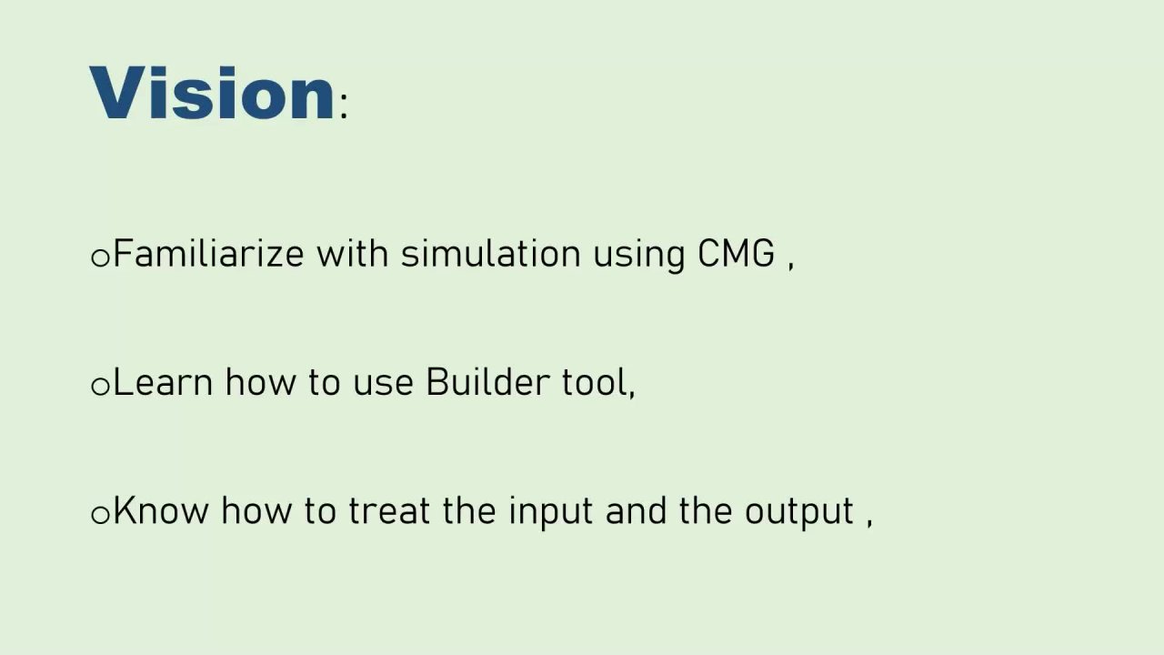
14. Conclusion: Hello, Welcome. So today we're just
going to run through what we've learned
throughout the course. We started by learning
block diagrams, catching. That was the first thing we did. From there, we learned
how we can transfer this block dance grams
intro PCP schematic. We saw with flippantly referring to how are
things connected. And the block diagram allowed
us to see the connection. Once going into microcontroller, What's leaving our
macro controlling? We also learned how to add various libraries in a goo from the board layout and manual
and automatic routing. I show you how you can switch between the boats when
you are out in manually. So you can start from the trope, we can switch to the portrait. And I also showed you how you
can do this automatically ingest lead the eagle
software route for you. From there we went on to see how they both
can be printed, talking more in detail, but they gave a file
and also weigh exactly. Can you order a
PCB to be printed? Now that we are done? Is time for projects which you
really have to white corn. What you are going to do is to build an automatic
change of a switch. This is base color
going to follow the same procedure that is drawing your block diagram. How is everything connected? Why is it making up the system? So you need to research more about the automatic change
of a switch in case you don't know much about
it from the can see dry need you
make your decisions. For now we are not
really specifying match on much on you being able to draws PHRs to
support your choices, but you just have to
make your own choices. Then from there, go on
to do the PCB schematic. You lay the board into route. Then if you want, you can save your file and print it to just
show your achievement. It has been an
interesting course. And I owe Fifth length something in our
course, PCB design. And up next, we're going
to talk about, okay, So let's say you actually have the library
that you are looking for in ego went to run through
how we can generate your own library in
the mixture to follow, to follow me for any updates. Once I published the
course on how to design your own library,
Autodesk Eagle. Thank you so much. See you in my next course.
 Brian Tafadzwa Gomora, Enthusiast