Transcripts
1. Introduction: Hello and welcome to my class, design and build your own chair. In this class, you
will learn how to turn your unique furniture
designs into reality. I'm going to walk you
step-by-step through the entire design and
manufacturing process, showing you how to
harness the power of CNC milling tools to make a chair in two different colors and with two different
decorative patterns. The chair is easy
to assemble and disassemble and requires
no glue or bolts. Some of the key lessons you
can take away from this class are how to design the entire lifecycle of
a piece of furniture, how to make a model
of your chair, how to prepare your
files to be cut, how the size and
the availability of materials can
impact your design, how to make prototypes, and finally how to make your chair look
beautiful in photos. Hi, my name is Anna Marcu. I'm a licensed architect and with this class I want
to teach you how to free yourself from
furniture choices you have in conventional shops, and build your own furniture into colors and shapes
of your choosing. For this class, I
have partnered with my friend Alex from
FabLab Bucharest. Hey, I'm Alex, Master Maker of Disaster at
FabLab Bucharest, Romania. Here at FabLab,
you have access to a wide range of materials and
machines like 3D printing, CNC milling, and laser cutting. We're providing you with
the opportunity to play, create, mentor, and
invent almost anything. Have a look at the website of your local Fablab to learn
more about their services. You can find them at fablabs.io and insert your country
in the search bar. There, you'll find a list of all available FabLabs
in your area. If the closest FabLab
is not that close, you can also google for CNC milling and your town
name and you'll probably find a job-shop or a
makerspace that could help you as FabLab Bucharest specifically is
made out of a team of professionals who will
make your ideas for you. We have worked on a wide variety of projects from
custom furniture, real estate moguls, trophies, shop signage, you
name it, we make it. I hope that by now you are really excited to
take this class. Are you ready? Let's
start the class.
2. Two Inspiring Books: In this lesson, I
want to talk about the book that
inspired this class. It's almost like a
handwritten cookbook, but for makers and designers. I think that if you love making furniture with your
hands or with machines, you are going to love this book. The book or more to the point, the books I'm talking about are Nomadic Furniture
Volume 1 and 2, by Victor Papanek
and James Hennessy. Victor Papanek and
James Hennessy were design mavericks of the '70s. They criticize
contemporary designers for failing to address the people
who need design the most, like the rural poor, the black, and the white citizens
of the inner cities. Instead "create a
whole new species of permanent garbage to clutter up the
landscape by choosing materials and processes that
pollute the air we breathe." It's interesting that
they were making such statements in the
'70s because in 2021 the problem of pollution and no recyclable garbage
is even more important. From these statements, you understand that they
wanted to use design to ease suffering and
create social inclusivity. They wanted to empower the less powerful and they cared
enormously about the environment. They also wanted
to install a sense of freedom in their readers and to give solutions to a problem the two writers
were experiencing, which is moving every
couple of years. They wanted to create
furniture that is easy to make, folds, stacks, inflates or knocks down, or else is disposable while being ecologically
responsible. True to their values, their books are a collection of smart and sometimes quirky
designs that people can do in their garage from widely available
materials like wood, cardboard, or
recycling materials like buckets and
barrels and pyres, all sorts of things
which you can build with relatively
simple tools. The designs found in the book
are a collection of ideas, both from the designers themselves but also
from other companies or designers whose products
fit the nomadic lifestyle. They also offer cheaper, more sustainable versions or DIY alternatives
of those designs. Both books are written
and drawn by hand, which makes the DIY idea
even more palpable. Many of the ideas
of the book can be found on the shelves,
like here today. The sawhorse, the foldable
tables and chairs, the plastic drawers, the
suspended bookshelves, the logo lamp, and
so many others. I encourage you to find the
book and browse through it. You can find many of
the pages on Pinterest, but you can also buy
the book online. I've even seen some free
PDFs circulating online. If you love making
things like me, you will find it very hard to resist not making one
of these designs. I was not able to
resist this chair. The two writers found the
design of the chair available in the '70s at Kold
Mobler in Denmark. It was offered lacquered in charcoals with white cushions. But the authors of the book offer an alternative
from plywood. They give dimensions
in inches and the construction scheme for the parts that looks
too simple to be true. I absolutely love this design. In the next class, I want to talk about why this chair has so many
important qualities. We choose a maker or a designer, we'll need to take
into account if you want to save time, money, and you generally want
to do your part in reducing the carbon footprint
on the environment.
3. Why This Chair is so Cool: Now that you understand
where this chair comes from, I would like to go into its outstanding
qualities which you as a maker or designer might want to take
into consideration, not just for this design alone, but for further designs as well. I believe they will
be useful to you, even when it comes to deciding
on what furniture to buy. In order to explain
these qualities, I first have to talk about the life cycle of a
piece of furniture. What do I mean by that? Well, a piece of
furniture has a life of its own that goes
through roughly six phases. First, you have
the raw material. The raw material goes through a manufacturing process to
make a piece of furniture. The piece of furniture is being transported to the customer. You as the customer might
have to assemble it if it does not come assembled
from the factory already. For a while, you
use this piece of furniture and when you
can no longer use it, you have to dispose of it. You as the designer of the chair are designing not just
the chair itself, but all the phases in the life cycle of that
piece of furniture. You decide the materials, the manufacturing process, who, where, and how assembles
this piece of furniture. How are you going to package and transport this
piece of furniture? How will it be used and
equally as important, can you dispose of
it in a way that it can be recycled and upcycled? You as the designer
need to think not just about the
design of the chair, but also think practically, sustainably, and budget
conscious of all these phases. Now let's go back
to the qualities of our chair from the
perspective of its lifecycle. Let's look at the raw material. When it comes to the
material of our chair, it's a board of plywood which is widely available and
locally sourced. The making and the
transportation of the raw material cost little and has a small
carbon footprint. Let's look at manufacturing. Because we use only wood
to make the entire chair, the complexity of the
manufacturing is also reduced. There is no glue or
metal bolts involved, no other materials like
plastic or upholstery. The making process
is pretty swift, which impacts tremendously
the manufacturing cost. Assembly, a lot of
pieces of furniture come fully assembled
from the factory, which means that in
the cost of the chair, you need to include the cost of labor needed to
assemble the chair. However, if the furniture design is simple enough that you, the end-user, could
assemble the chair. Then the cost of this chair
is much lower for the ability of the design to be included in a flat package is
highly important. Transportation.
Let's think how you transport a piece of furniture from the factory to the user. You can transport it
in a flat package containing only the parts and the user puts the furniture together or you send
it already assembled. If you send it in
a flat package, the overall volume
that it occupies in the car is a lot lower, which means that the
transportation cost included in the price of the chair
is a lot lower as well. This design not only
helps the manufacturer of the chair keep the cost
low for you the user. But if you the user
has to move houses, you will not have to rent
such a big car to transport your items because you will be able to stack them together. [LAUGHTER] An added bonus to this design is bringing
this chair up the stairs, which will be 10
times easier than bringing any already
assembled chair. Let's look at the usage. When it comes to usage, you the designer want to create a design that will make the user keep that item in their home for the most
amount of time possible. How do you do that? Well, aspects like beauty, durability, how easy
it is to clean, versatility become
very important and our chair scores high on
all of these criteria, particularly when it
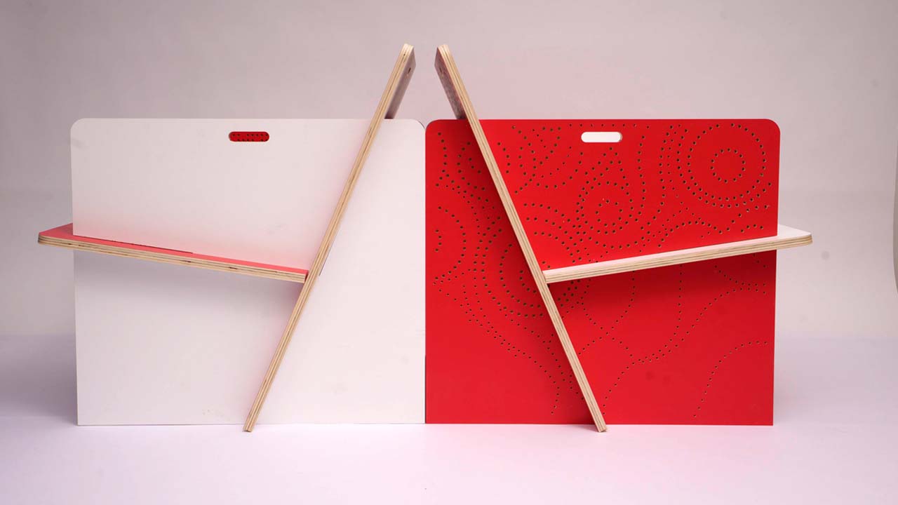
comes to versatility. One of its great
advantages is that you can change up the
faces of the parts. You can have a chair
that is red on the inside or white
on the inside. You can change it up depending on the mood
you want to achieve. The fact that you can
assemble and disassemble this chair means
that you can use it for temporary situations like on the terrace in the summer
when you have family visiting and you need an extra chair
is especially useful if you live in small spaces and you don't need an armchair
all the time. But in those cases, when you do, you can put it off for
as long as you need and then store it
away in a closet. Disposal. Finally, if you decided to dispose of the chair, you can absolutely put it in
the recycle bin for wood. There are recycled yards for
wood all over the world, so bringing some stacks of
wood there would be very easy. Imagine if your chair had also some metallic parts or
plastic parts and some sticks that are upholstery
all stuck together and unable to separate
without breaking it apart. How difficult to
recycle that would be? Not this chair. You don't have to break it, you don't have to recycle
the components separately. Just some planks of wood
stacked together in a pile. The chair we're about
to do together in this class scores high
on all categories. Availability of material,
ease of manufacturing, whether you want to use a
CNC milling machine or not, of transportation, of assembly, of use and of course, recycling. I hope by now you
are excited to make this chair now you're able to see it as more than
just its final shape, which is delightful to watch, but also of the
value that it has to bring in making
your life easier, not burdening your budget
and saving the environment. Now let's have a look at
the tools and materials you will need in order to
successfully complete this class. See you in the next lesson.
4. Software, Tools and Materials: In this lesson, I'd like to
talk about the tools and materials you need in order
to create this chair. Depending on the phase in
the project that you are in, you will need different
tools and materials. In this project, there are
essentially two phases; the planning phase
and the making phase. For the planning phase, you need SketchUp, which is a 3D modeling
software that I have used the model and modify
the design of this chair. You can find SketchUp in different pricing tiers
depending on what you need. But for the complexity
of this class, you can easily use their
free web-only version. I happen to have
their pro version because I have a business
but if you want, you can also use the pro version for free for one entire month. If you have skills in other
3D modeling softwares, I have left an OBJ and DWG
file off the original chair in the project and resources
section so that you can modify it in whatever
software you want. Just make sure that when
it comes to cutting time, we export the file in
a DWG or DXF format. If you do not have a
3D modeling software, you could modify
the cutting files in Adobe Illustrator or AutoCAD, which you can also use
for one month free. You can modify the contour
and add any pattern you want, then print it on
a piece of paper, stick this paper on a piece of cardboard in a smaller scale, and make yourself a physical cardboard
model of the chair. The final cutting files that
need to be handed out to the CNC milling machine
operator have to be DWG or DXF, which many 2D and 3D
softwares can achieve. Just have a look into the export settings of
your desired software. Work on a laptop if you can. There were a couple
of occasions where I felt I said everything to Alex, only to realize a location that I had to make some changes. It was useful that
I had my laptop with me to make the
changes on the spot. I also used a notebook
to sketch out ideas, as well as some packaging
cardboard to build a physical model at a smaller scale early
in the design process. Now, let's have a look
at them making phase. In order to make the final chair and the prototypes
leading up to it, you need a different set
of tools and materials. For the first prototype, we use an 18-millimeter
thick plywood board that was 38 by 90 cm. For the American students, this is a board that is
three-quarters of an inch thick, that is 14.9 by 35.43 inches, and we use spray cans to
color it on both sides. Any spray cans will do. Just make sure you protect your eyes and mouth
during the spray. Or like Alex, you spray it in a specially designed space that sucks all the spray
particles out. For the second prototype, we use another 18-millimeter or three-quarters-of-an-inch
plywood board. But this time we had more
surface to work with. This time we tested them
on a board that was 125 by 200 cm, which is 49.21 by 78.74 inch. The final prototype was cut
on an even bigger board. This time it was 187 by 252
cm or 73.62 by 99.21 inch. Again, same thickness as before, 18 mm or three-quarters
of an inch. Both these boards were painted with the
same type of paint, which is this one. Unfortunately, we
were limited by time and the local store only
had water-based paint, which made the board
curve a little. If you can find a paint
that is not water-based, that might actually be better. The paint was rolled on with a roller in two different
colors on both sides. If you use two colors like
I did, use two rollers. Finally, the cutting
machine used is a three axes CNC
milling machine. The three axes mean that it
drill moves back and forth, left and right, as well as
up and down, three axes. The other thing that you need to remember is that the surface of the cutting machine
should be bigger than whatever board
you want to cut. The advantages of using a CNC milling
machine are not just in the effectiveness of
cutting the chair parts, but in the versatility
of decoration you can apply to the
surface of the chair, which would take a human
being a lot more time to do. Since this is a
class for makers, I believe we could all
learn from each other, and I encourage you
to make the chair, even if you use classical carpentry tools
to cut and decorate it. I don't have any, which is why I asked the FabLab to collaborate with me on this, but if I did, I would most surely
give it a go and I have no doubt that it will
look just this fabulous. So now that you
have an overview of the tools and what you might need going through this class, let's see if we can understand the chair
and its components.
5. Component Dimensions: Now that you have an
overview about the tools and materials we're going
to use in this class, let's figure out how
to make this chair. There are a couple
of questions that came naturally to my mind. Do I understand what the dimension of this
chair component is? Do I know how long or
how wide they are? Do I understand the location
and the angle of the slots. I'm going to walk you through my thinking process
because it will be useful to you more than
the design of this chair. Especially for those working
in the metric system, not in the imperial system, this lesson is
particularly useful. I encourage you to take out
a notebook and a pen and to start sketching the shape of each of the components on paper. The shape doesn't have to
be proportionally correct. Just make some rectangles
and right next to them, what part they should be
if it's the backrest, the armrest or the seat and
write down their dimensions. I made the sketch in inches
and then in centimeters, and I made use of a
calculator to figure out how big the components are in centimeters because this is ultimately the unit
I want to work in. But you just write down the units that are
important to you. For the people working in
the metric system like me an inch is 2.54 centimeters. I started with the seat and the backrest because they
looked very similar. We know they have
to be equally wide. The slots for the
armrest have to be equally far away
from the edges, and the slots themselves
have to be equally thick. I just put the dimensions
on paper for myself. If that was too quick for you, here are the dimensions
of the seat and the backrest in inch
and centimeters again. In the following step,
I had to look at the armrest and ask myself to
understand its dimensions. Do I know how long
or how wide it is, and do I understand the
inclination of the slots because they are not 90
centimeters anymore? Again, I made this sketch first in inch and then in centimeters. I put down all the dimensions
I could understand. The armrest is 30 inches wide, just like the seat, and the backrest
in 24 inches high. The seat slot starts nine inches away from the top edge
and it's 10 inches long. The backrest slot is 13 inches long and should
start about four inches away from
the side edge and should end nine inches
away from the side. On the right side you see
my sketch in centimeters. While I put all this
information down, I realized one thing
that the backrest has to be 26 inches long or 66.04 centimeters in order to touch the ground and the
seat has to be 20 inches or 15.8 centimeters in order
to touch the backrest. This is because of the slots belonging to the other
chair components, namely the seat
and the backrest. The inclination of the slots really depend on
these dimensions. Here you have all
the dimensions, both in inches and in
centimeters grouped together. I made a little animation to
show you how I understand the inclination of the
slots in my mind thus far. If I start with the
shape of the armrest, then the inclination
of the backrest is where an arch with a radius of 26 inches
meets the lower edge and the seat is the point where an arch with the radius of 20 inches is going to
meet the backrest edge. Otherwise I cannot bring the
seat and the backrest in. At this point in the
development of the design, I don't know if the slots go
above or below these lines, but this is something we'll
absolutely have to look into in more detail
in the next lesson.
6. Physical Model: I don't know about you, but I'm very curious
what a chair looks like. So at the moment
that I understand the scale and dimensions of each of the components
is the moment that I actually want to
start making a model. You might be wondering, why should you be making a model or what does
this model do for you? Making your model is one of the best ways architects and designers can test their ideas. When you have a physical
model in front of you, you can immediately tell how
materials work together, how the joints work. You have information
about the overall scale, the shape, the color,
and the proportions, as well as details that inform you about changes you
should be making, and all these before you
build the final prototype. Models are a smaller, more cost-effective version of the real thing we want to build. You want to make
all the mistakes in this phase because
it's cheaper. The first model I want to make for this chair is
from cardboard. I wanted the model to be
quite big and I try to figure out what would be a good
scale to build this model in. Should it be a third, or maybe a quarter of
the original chair size? Just thinking about all
the fractions I will be doing in my head
made my head spin. What I did instead, and this might not be the
most orthodox approach to it, is to say that one inch is one centimeter and
in this scale, I can make a
relatively large model that will be
proportionally accurate. If you work in the
imperial system, you might have to
try a few things. You might decide that 10 inches from your chair is two inches in your model and thus
build a model that is 20% of the original size. Or maybe you decide that
10 inches is one inch. You will have to
test a few things to find the right size
model for you. But for me, translating one
inch to one centimeter, give me the right size model. To construct my model, I took a bunch of packaging
envelopes that I had laying around and I cut the
components out of them. First, I did the
contour of each of the components and then
I cut out the slots. As the cardboard is
one millimeter thick, the slots also had to
be one millimeter, which is not a lot to cut out. For the arm rest, I used a compass and a ruler. Initially, I thought that the meeting point between the seat and the
backrest would be at the intersection between
a 20 centimeter arch with the 13 centimeter arch. But unfortunately, if I
continue the backrest edge, this will turn out to be longer
than the 26 centimeters, which we need to have. I went back to my initial theory that the seat is actually at the intersection between
the backrest edge and the 20 centimeter arch. I mark my slots and I carve
one millimeter out of them. Let's assemble the components and have a look at this model. What can you learn from it? Right aftermath I understand
that this chair is more of an armchair and it's pretty massive even by the
standards of an armchair. Between the two arm rest, I have 62.24 centimeters. Normally, armchairs are about 55 centimeters wide so it's a very, very
generous armchair. The width of my chair is a lot, which is why my cardboard
seat is turned into an arch. I hope that the 1.8 centimeter
plywood board would hold because my thin cardboard surely doesn't at this span. It makes this nice
curvature in the middle. I'm also noticing the angles of the armrests
and the backrest. They put me a
little on the edge. If you remember from my class, home office interior design, I mentioned that the
edges trigger fear. They make us feel inhibited. I'll make a note for myself
to take care of those edges. The last thing that I
notice is the places where the seat
meets the backrest and the backrest
meets the floor. These are points that will need more attention when
making the chair. In order to look closely
at the details and to do a precise design object, a physical model should be
accompanied by a 3D model. Now, if you have the
money and the resources, you can continue with physical models after
this point as well. But you can also save yourself
some time and money and continue in a virtual space
by modeling the chair in 3D. In the next lesson, I'm going to teach you how I
model the chair in SketchUp.
7. 3D Model: Now that we have
a physical model, let's model it in 3D. It will allow for more precise
and cost-effective design. The way I did it is that I model the chair in a software
called SketchUp, but you can model it in any
3D software you know as long as you can export the
files as DWG or DXF. I would like to
specify beforehand that even though our
model is very easy, this is not a SketchUp
modeling class course. I will show you how I'm thinking about the design
and its geometry, not which tool I am selecting
in order to model it in 3D. If you have never
used SketchUp before, I encourage you to
first go through the essential modeling
tutorials from SketchUp, which you'll find
on the website. The SketchUp tutorials are free. You can go watch all of them in a couple of hours and no more. They are very fun
and easy to do. When you are done with the modeling tutorials
from SketchUp, come back here to
model the chair. Everything I will
explain will be super easy to
understand afterwards. SketchUp is a 3D
modeling software, and for the model of this chair, you can surely use
their free web version. Because I'm a business, I use the pro version
and you can try the pro version as well
for one month for free. If you're advanced to
SketchUp modeling, you can also skip this part and download the SketchUp
files I have left for you in the Downloads
and Resources section and proceed to
the customization lesson. Let's start modeling
in SketchUp. First, I'm going to
model the backrest and draw a rectangle and I
put the dimensions in. I measure them with my tape measuring tool just to be sure. I turn my rectangle
into a component because I intend to
make more copies of it. I use the guidelines
to create the margins. I add one more guideline on
each side to mark the slots. Because I work in
the metric system, I have added 1.9 centimeters
as opposed to 1.8, which is thickness of my board. Because when I joined the parts, I want to work the
slide in easily. I gave it a bit of a workspace. The length of the slots are
33 centimeters or 13 inch. I mark the edges on my slot and delete the unnecessary
faces and edges. Finally, I extrude the
face of the backwards. The last step is to delete
all the guidelines. From this it is easy
to create the seat as it is a smaller
version of the backrest. So I copy the backrest and
I made my component unique. To make the component unique, then whatever changes
we are going to make to the seat are not going to
influence the backrest. I draw new guidelines marketing the length of the seat and the
length of the slots. The length of the seat is
55.8 centimeters or 22 inch. I just pull the edges of the
seat to meet the guidelines. The length of the slots are
25.4 centimeters or 10 inch. Finally, I delete all the guidelines and
our CV is complete. When it comes to the armrests the construction is a
bit more complicated. I'm going to show you over diagram how things
should be constructed, and then I'm going to
show you how I model it. Let's look at the diagram. Firstly you create the
contour of the armrest, which is 76.2 by 61 centimeters or 20 by 24 inch
according to the sketch. Then I create a
guide from the side. Because I want to know where the backrest meets
the lower edge, I create an orange that is 66 centimeters or 26
centimeters long. Where it meets the lower
edge of my armrest, that is the angle where my
slot is going to be built. In order to create the
thickness of the slot, I draw a guide, 1.9 centimeters
towards the seat. Then I define the
length of my slot, which is an arch
that has the radius of 33 centimeters or 13 inch. Finally, I want to build the slot where the
seat is going to go. To do that, I create
the guide that is 23 centimeters or nine
inch from the upper edge. Then the second guide
from the lower edge, that is 13.5 inch or
34.4 centimeters. Again, the slot thickness is 1.9 centimeters or 3/4 of an inch. As mentioned before, the slot
should be 1.8 centimeters. I decided to leave one
millimeter tolerance for the woods to
slide in easily. If you work in in inch, you should leave a
bit of tolerance to as 3/4 of an inch
might be too tight. Finally, I draw the length
of the slot with an arch of 25.4 centimeters or 10 inch to determine the
angle of the seat. Then we draw the slots between
the arches and the guides, and we are finished. Here's how I model it in case you miss the
instructions on the diagram. Now it's time to
assemble the parts. The most important thing
you need to remember about this part is that you need
two sets of components. One set is lying flat
on the floor and the other set is
an identical copy that you use for your 3D. The reason for that
being that if you change anything about the
elements in the 3D chair, the elements on the floor
will change as well. You need the elements
of the floor because those are the ones who are
going to send to be cut. You look at your 3D and you modify it based on your wishes, and then you're cutting files on the floor change automatically, and that is pretty neat. You change your cutting
files in real time, make sure to make a copy with
the option plus Move tool. Here's how I assemble the parts. I first rotate my armrests
copies to sit upright. Then I make sure I place them at the distance between
the armrest, which is 62.4 centimeters. I bring in my backrest. I've placed the backrest
in position and I rotate it along the
edge of the arm rest. Then I push the backrest in
the position it needs to be, and I do the same
thing with the seat. Finally, this is what
my chair looks like. Now that we have
our basic model, I want to start
researching materials for which you cut out the
elements of my chair.
8. The Standard Plywood Board: Once I have finished
my 3D model, I send it to my friend Alex
from FabLab Bucharest, and I asked him what
his first impression was about the design. What do we need and how
could we make this? He asked me about the
overall dimensions of the chair and the thickness
of the board that I needed. I said that based on the sketch, it's 3/4 of an inch
or 1.9 centimeters. He told me that there was
no 1.9 centimeter board, at least not in Romania, and we can have either 1.5
or 1.8 centimeters board. I wanted to be on the safe side, so I picked the 1.8 centimeters. In case all my components
were equally wide, I thought that the most
efficient plywood board I could find is 30 by 102 inch or 76.2 by
259.08 centimeters. If you take away the surface of the material necessary
for the slots, you've essentially thrown
away less than 1% of the raw material needed in
the production of this chair. This is really smart design. I think Alex must have
laughed at me because a standard plywood board
in the dimensions of 76.2 by 259.08 centimeters
simply does not exist. Plywood boards come in standard sizes predetermined
by the industry. No matter for you guys
watching who intend to make this chair with the
tools from your garage, you might be able to go to a hardware store and ask
for a board of this size, which usually is cut out from a bigger board by a personalized
service of the store. It might not be available everywhere but honestly
it wouldn't hurt. In Romania, the FabLab Bucharest works with a wholesale
distributor of construction materials
and you can buy all sorts of things off their website
including plywood boards. Alex instructed me to have a look at their site and decide which board I wanted to have because they come in
all sorts of sizes. He also instructed me
that I should only look at boards that are
qualities of B/BB, BB/BB, and BB/CP. Anything else would not
have been useful to us. Now, what do all
these letters mean? It means that plywood
boards come in different qualities depending on what their intended
purpose might be. If you intend to use a plywood board to make
a wooden toy out of it, it should have different
qualities than if you use it as a filler layer on
a construction site. Plywood boards are made of
different parts of the wood, and different types of wood, they have different resistances
and different finishes. Looking at these qualities and knowing what they
mean is important. The plywood you find in your area might not
be labeled the same, but it will be for
sure differentiate by specific features and if
you are aware of this, then you will know
what to look for based on the requirements
of your design. What also might matter to
you is the type of wood. Some Some are more
resistant than others, the color of the
board also counts. Be aware of these
things when you look for the best board
for your chair, and make sure it is clear to you what qualities matters
and which don't, because they also
impact the price. Now that we understand
the boards, it's time to look at how to cut the components
out of them. But do we change the design
to fit the plywood board, or should we find the board that would
best fit the design? In the next three lessons, we are going to explore the pros and cons
of these decisions.
9. Arrangement of the Components: Before we start placing our
components on the board and finding out which plywood
board is the best fit, we need to know how to
place the components, and this is dictated by how
the board is being cut. Here's what you
need to understand. The components are
being cut with a drill. The drill cannot
cut the piece from the side like you would
with a normal cutting tool, but it cuts out the shape from the inside of
the plywood board, and this is for a good reason because
due to the high force, the component might break
or move from their place, so they need to be
locked on all sides. This is why my friend, Alex, from FabLab, advised me to leave between
seven millimeter to one centimeter on all sides of the components so they can
be cut out of the board. These margins have
additional use other than keeping the
components locked. They are also the
available surface needed to add nails
to the board. You see when you deal with
a large board such as mine, you need to fix it on the cutting board
in multiple places. You can't do that on the surface of the components
because you need them for the chair but you can't do that on the
surface in-between. Because of the specific
cutting tool we use, we need to find a board that would fit not
only the components themselves but also the space between the components
and the margins, otherwise, we cannot use it. With this understanding,
I started arranging my components on the
various size board and see what I would get.
10. Fitting the Design to the Board: When creating any design, you want to be mindful of
the material you use and focus on minimizing to the
best of your abilities, the amount of waste you
produce during cutting. But being too focused
on that can have some dire consequences
on your design as well. In this lesson, I would like
to share some mistakes I did trying to modify my design in order to
diminish the waste. Initially, my friend Alex from FavLab mentioned
that one of the most easy to find boards is the
one that has a dimension 2,500 by 1,250 millimeters
and so I started with that. In the middle of my sketch up
drawing in shades of gray, you see the original design
placed on this board. Because more than half of the material would become waste, I decided to modify
my design in order to place two chairs on the
board instead of one. On the left side of my
sketch out drawing, you see a modified version of the chair in the colors
blue, green, and pink. In this version, you throw
away very little waste and you can use it for two
chairs instead of one. The first move was to make the original design less wide so that two chairs could fit on the board because the
arm rests narrowed, the seat with narrow as well and because my plywood board
is not long enough, the upper side of the
back rest would be cut. When you put the components together and have a
look at your design, you can spot all
possible problems. On the left in gray, you see the original armchair, and on the right
side in green, blue, and pink, you see the
adapted armchair. From a technical standpoint
this chair could be achieved, but from an economical
standpoint, I was not so pleased. First of all, the
original design is actually an armchair
and as such, is designed a little
lower to the ground. But if the arm rest
are closer together, then it is a chair
and it feels rather uncomfortable to sit so close
to the ground on a chair. Normally chairs are at least 45 centimeters away
from the ground. You also can't lean
so far back in a chair as you do
in an armchair, so most likely the
inclination of the backrest would have
to be readjusted as well. Also, the backrest had
to be chopped because it could not fit in the
standard plywood board, so there's no real
backrest to lean on. The edge of the backrest, falls below the shoulder blades and it could feel uncomfortable. I simply could not imagine
anyone sitting comfortably for more than 20 minutes
on this chair so I decided not to
pursue this design. If you're limited by
cost and time and you need some temporary
seating quickly, you could produce
these chairs for a temporary situation like an outdoor cinema or
a venue of sorts. But it's definitely not
good design in my opinion. I decided not to pursue
this idea because it lacked a little bit of the economics of
the previous chair. I didn't wish to give
up on the idea of putting two chairs
on a plywood board, so I started looking for plywood boards in
other dimensions. It often happens that the plywood boards
are out-of-stock, but Alex from FavLab suggested the board
with the dimensions of 2,500 by 1,870 millimeters, which is sold on auto
stock and easy to find. I place the chair components
on it and I adapted the parts so that one centimeter is left around every component. In this case, the chair is as
wide as the original chair. Just the backrest
would be cut off. At the time I'm
recording this lesson, I've already finished making
the chair and working with some prototypes give
me a new perspective. When I was testing
these models in 3D, I thought that the chair
would be too short. The arm rest are one
centimeter shorter. The seat is closer to the ground and the backrest is
shorter as well. I was not sure it would
be so comfortable and I did not want to risk
making it just to find out. I did not pursue this
design, but in retrospect, I realized that this
design is actually okay and with a bit of
prototyping and testing, it might prove to be a very efficient and
cost-effective design. But back then, I was
not so confident, so I decided to leave it here and instead find a board that would fit as closely as possible with the original
size of the chair. What I learned from
these exercises is that why cared very
much about not wasting material they should not overpower the quality
of the final design. Always aim to make
a great design for the people sitting in
the chair and if you can adapt it to reduce the
amount of waste without changing how people feel
in the chair, do it. Otherwise, saving
material and creating an uncomfortable chair is
a waste of time and money, especially if you intend
to sell your design. So in the next lesson, I will take the
opposite approach and I'll go through a multitude of boards to find the one
that fits my design the best.
11. Fitting the Board to the Design: In the last lesson, I tried feeding the
design to the board. But in this lesson, I would like to fit the
board to the design. What I mean is I
will look through all available sizes to find the one plywood board that
is the closest to the shape of my components that will produce the least
amount of waste. I made a list of every size board under
the plywood qualities I was instructed by Alex to
look into. Here's the list. Here are all the sizes laid out. Once I place my chair
components on them, I could see
immediately which ones fit and which ones
did not fit at all. for example, the board 2,000 by 1,250 millimeters
would not work at all. I could not even fit
one chair on it. Then I found three size boards that could fit all the
components of one chair, but will create a fairly
large amount of waste. These are 2,440 by
1,250 millimeters, 2,500 by 1,220 millimeters and 2,500 by 1,250 millimeters. Then I have two
boards that allow for the cutting of
one-and-a-half chairs. These are 2,500 by 1,700, and 2500 by 1,500 millimeters. If this would have been
a project where I was sure a lot of
chairs will be cut, I would definitely consider these two plywood
boards as an option, but as I wish to do only
two chairs for now, I'm looking for either
a board that can fit one chair or two
chairs really well. The board that helps me make one and a half chairs is not
really useful at this point. I'm left with my last
two best options. My first option is to use a
plywood board in the size of 1,525 by 1,525 millimeters. The components are covering
it from corner to corner, which means that they'll
have to modify them by one centimeter left and right and make the chair
a little narrower, but it would not
have to be shorter, which is really no
problem for the design. The other option that
fits really well is 2,540 by 1,870 millimeters
which is a massive board, but on which we can
place two chairs. I had to look together
with Alex from FabLab at the availability
and price of these boards, and we agree that
the big one would be a lot cheaper than buying
two smaller boards. Alex contacted the
distributor only to find that the board
was no longer on sale. But actually a very similar
size board was, it was 2, 520 by 1,870 millimeters and so I decided to use this
one for the final chair. However, I felt that before
we cut the final chair, we should at least test our
design a couple of times. On this occasion, we also decided to buy some
smaller plywood boards. One in size 2,000 by
1,250 millimeters, and then even smaller
one in the size 380 by 900 millimeters to make some prototypes before the
final chair would be cut. Now that we have all the
plywood boards beneath, it's time to think
about customization. What fancy details
will you make? How are you going to
decorate this chair? What colors should you pick?
12. Customization: Joints and Corners: By looking at the basic
design we have in 3D, I can see that there are some details that I would
like to change about it. These are my decisions, but feel free to expand on them when designing your own
version of this chair. The first thing I wanted to
change was the chair corners. As you remember from
my other classes, I have often spoken about the fact that round
corners generally make us feel safe and angular
shapes put us on edge. This chair is full of angles, so I have almost this
visceral desire to get rid of all those angles
pointing in all directions. I can already see myself
bumping my sheen into it. How do we do that? On the components lying on
the ground in my 3D model, I've decided to create arches of three centimeter radius
on every corner, and then push the remaining
shape of the corner on the ground thus eliminating
the edge completely. I've done it on
every edge sticking out except for the base of the armrest because I feel like the chair is more
stable that way, then those corners are
really don't bother me. Additionally to the corners, I felt that some details of this chair needed
more attention, and here's where I
made a few changes. First, I looked at the place where the seat
meets the backrest and realized that the
joint not look seamless. I did not like this v-shaped created between the
seat and the backrest. One adjustment that I made
is to change the angle of the edge of the seat
so that it would be parallel to the backrest, then extended disease until
it meets the backrest. I also wanted the backrest to
fall flat on the ground and not at an angle so that it would prevent the chair
from being wobbly, and also for the edge to break. I did the same thing to
the edge of the backrest. I changed the angle to be
parallel with the floor, and I extended the backrest
all the way to the floor. However, here Alex warned
me that he doesn't have the tools cutting edges of the chair in this precise
angle that I wanted. They have all tools, but farm lab is not specifically
a carpentry studio. Although I had designed
these details, we eventually were
not able to actually implement them in
the final design. Still I do think it's
worth telling you about it because maybe you have the access to tools
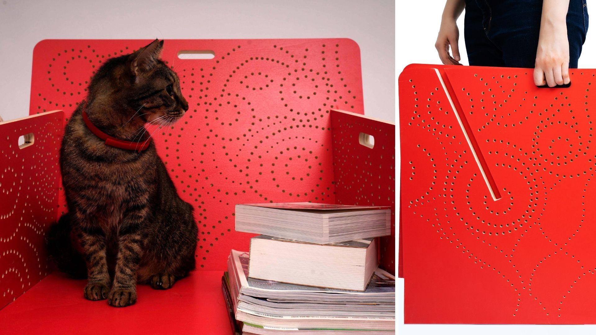
which can do that. Maybe you can do it at home. But in this case, we could not. The last thing I thought
about was manipulation. The components of
the chair are pretty big and with 1.8
centimeter thickness, they are heavy and
hard to manipulate. I needed some detail on each of them that would make it
easier for me to grab them. I added the hole on each
component that would allow a human to grab and
manipulate them with ease. In a first prototype, I made this hole in the shape of a circle to match the
other circles of my chair. But on the last prototype, a created a round slot
that would make it more intuitive for the user to understand that there is
where you grab the chair. Now that we have adjusted some corners and
joints I think it's time we explore the field of
colors and surface patterns.
13. Customisation: Decoration: We have altered the
corners and the joints. How else could we
customize our chair? I'd like you to feel
free and explore anything you want here
from carving techniques, engraving, cutting bits and
pieces out of the chair, using certain oils or
lax, anything you want. Look around at the tools
you have access to and figure out your
customization strategy. In this lesson, I
want you to go crazy. I looked around at what I had. I didn't have any carpentry
tools, I still don't, but I did have access
to a CNC machine which can do a lot of things in a very short amount of time, and I had color on my side. As much as I wanted to leave the chair in neutral colors, I thought that working with color would really
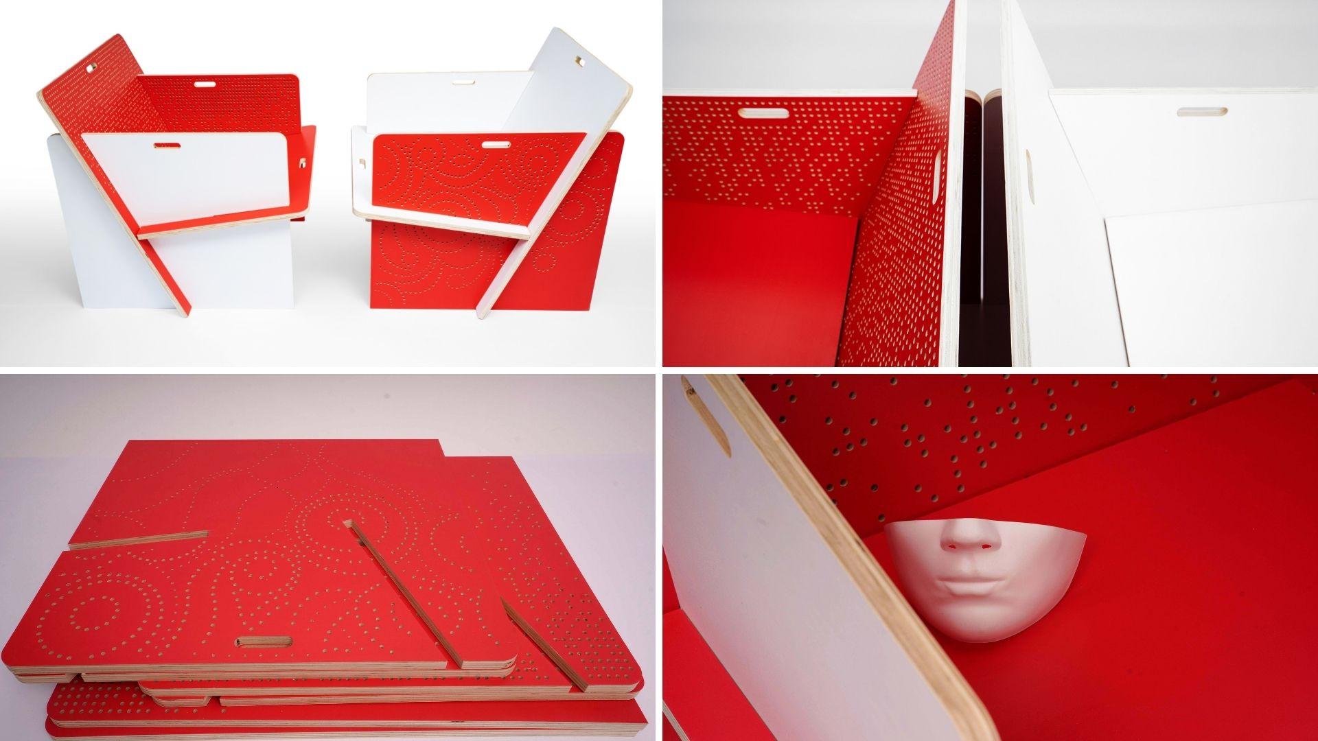
make it stand out. Let's have a look at color. I had this idea
in my head that I wanted to use some
strong bright colors, but I still wanted it
to look sophisticated. I tried a few colors
on the model, and I love the idea of working not just with one
but two colors. I could work with white and
red or white and leila. The interesting part
about this chair though, is that when you paint it
in two different colors, you can change which
color is facing the outside and which one
is facing the inside. Ultimately you can
assemble the chair, both of the white side
and the red side inside. I also love the idea
of making the chair completely white and
painting only the edges. Unfortunately, on talking
to Alex about it, he advised me not to paint the edges because as the
plywood is made from different sheets of wood
stack together does not absorb the color evenly. We will have some very
uneven colored services. Another aspect you
might consider is where the chair
will be located. If you decide to use
the chair outside, you need to consider
weathering and how it might withstand a
lot of water and snow. You might decide to add certain layers of coating
or leave some space between the sit and
the back lace to allow for the water to
spill off the chair. My plan was to use
the chair indoors or on covered tourist
during the summer months, so I left the protection
against the elements out. But if you plan to
use it outdoors, you might want to give
coating more thought. Now, let's have a look at
surface-patterned decoration. Another reason why I
love this chair is the amount of empty surface
that it has to offer. You can create any beautiful
patterns you want on it. You can cut parts out of it, make holes in it,
anything you want. I looked around for inspiration
on Pinterest and I found this really
interesting project of a cabinet on the
painted hive blog. I like the idea of
taking a lace pattern, scaling it up, and recreate it from
tiny little holes. As it happens, the holes were not made with the CNC machine, but with a Bosch bench drill. According to the blog, the great thing about
the bench drill is that there's a laser guide to make a lining the whole
easy and a hand wheel, which is nice and economic. You can also set the drill speed and depth to suit your needs. I wanted to show you
this just in case you decide not to
use a CNC machine. The project had 3,000 holes and it took six
hours to drill plus an additional sanding and using your file to remove the
splinters from the plywood. For the final project
of this chair, as you will see in this class, the CNC machine took about
two-and-a-half hours, not just to drill
the many holes, but also to cut the
components out of the chair. We also did not do any
additional filing and sanding. The overall making time
was considerably reduced. I looked around the internet
for patterns I could use, and I found this one. I inserted as a texture in
SketchUp and I applied it on all the surfaces of my model to test out what this
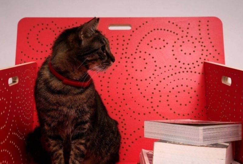
would look like. For my second chair,
I get inspired from a pattern that looks like
the ones in zeros of a code. I wanted the Yin and
Yang type of situation. One chair will be covered
with a pattern that is more floral and feminine
with curves and worlds, and another chair is covered
with a pattern that is more masculine, accentuating
straight lines. After testing my
idea with a photo, I decided to turn my patterns
from JPG to vectors. I created a circle component
and how recreated my JPG, I used two circle types one of six-millimeter diameter and one of four-millimeter diameter, and have applying
it all over my JPG. Finally, this is how
my design look like. I wanted to recreate a less
texture all over the design, and so I did not use
the circle sparingly. Now that I have showed you some ways in which you
can decorate your chair, I like to go into the
nitty-gritty details about how your files have to look so that the FabLab team and the CNC machine understand
what needs to be done.
14. The Cutting Files: In this lesson, I like to talk about how the files need to look like when you want to
cut them with a CNC machine. In order for the machine
to work appropriately, you need to export the files
either in DWG or DXF format. These formats can
be read by a lot of graphical programs
like AutoCad, SketchUp the software I'm using, and even Adobe Illustrator. In fact, you could
draw the components in Adobe Illustrator and export
them as DWG for the cutting. Whatever software
you decide to use, make sure that when you
press the Export button, the DWG option is there. The first thing you
need to know is that even though you model
your files in 3D, when you finally have
to send them to be cut, they have to be 2D. What I did is I took the
components that I placed on the final board and I deleted all the surfaces with
the exception of one. During the exporting process, I made a couple of mistakes, which I hope to spare
you from doing. My first mistake is to vectorize
my photo in Illustrator. Now, if you have a
very good JPG and you intend to cut out big
chunks from your chair. This idea might actually work. you important photo
in Illustrator, you vectorize it and then apply it to the surface
of your component. Then export the file as is DWG. When I sent Alex the
version of the model with the exported vectors
from Illustrator, many of the circles
were in fact ellipsis. Since I was using
such small circles, they would have to be made with a drill going in and
out of the plywood. For that, Alex said he needed exact circles with
a clear center. I redrew my entire pattern
with circles in SketchUp. I drew a four
millimeter circle and a six millimeter circle and I create the component
out of each of them knowing that any
change I would make to one circle would affect
all same size circles. Another mistake that I
did was to send Alex the lines not as vectors
but as disconnected lines. This again was not
helpful for the machine. Always make sure that you send connected vectors when you have elements you
want to cut out. Before finishing
your design don't forget to leave a margin
between the edge of the component and
the closest hole of about one centimeter so that the component does
not get destroyed. Alex also asked me
to differentiate my layers when sending
him the files. The board have to be one layer, the chair component would
have to be another layer, and the circle
layer would have to be differentiated on size. One layer for the six
millimeter holes and another layer for the
four millimeter holes. Ideally for easy spotting, the layers would also have to be differentiated by colors. Then you select the top view of your SketchUp browser
and press "Export". Here you do something
less than intuitive. You select the 3D model option and when you go for options, you select the edges and
the AutoCad DWG file. You can also draw your 2D components and
their decoration in 2D, in Illustrator, or even AutoCad, and export them as
DWG or DXF files. Now that we know how to
cut and export files, we need to start prototyping.
15. The First Prototype: For the first prototype, we took an 18 millimeter or 0.7 inch plywood board that is just 38 by 90 centimeter
or 14.96 by 35.43 inch, and we cut out two fragments from the chair that will
be joined together, namely a piece of the seat
and a piece of the arm rest, but from two different chairs so we can observe the two patterns. The board was spray
painted on both sides. One side white, and
the other one pink. The spray painting took
place in a spray painting designated room with an air suction machine
attached to it, making sure that
the spray particles would be sucked out of
the room immediately. That being said, you should
also do everything to protect your eyes and mouth
with a mask and sunglasses. The spray can that Alex used is called Loop Pro Writing Tools. It covered the surface
evenly with only one layer. But I'm sure you could
use other spray cans too. We waited one hour
for them to dry. Although the pink side
dried out pretty quickly, the white one needed
a lot longer to dry. We thought we should
proceed anyway, since this was just
a test and we were eager to see what is
going to look like. As you may have guessed, this prototype comes
with a specific drawing. Although I had my
original drawing panned out on the size
of the final board. I still needed to create a new drawing that fits
the new size of the board. As mentioned before,
for this prototype, I decided to cut out a piece of the seat and a
piece of the armrest. I place them on my
designated board, which was 38 by 90 centimeters
or 14.96 by 35.43 inch. The way you draw that
is pretty simple. You make a rectangle that
is 38 by 90 centimeters, or whatever size
your prototype is, then you place the shapes of the seat and the armrest on it. You create the one
centimeter margin around the edges of the board, and where the margin
intersects your shape, that is where you cut the
shape you want to test, and don't forget you also leave one centimeter
between the two shapes. As mentioned before,
there's one more step you need to do before you send
the drawing to be cut. You have to separate the
layers by type and color and the lines have to be exported
as closed edges only, no surfaces, as 2D drawing. Please review Lesson 13 for
a detailed explanation. To cut our plywood board, we use the CNC milling machine, used specifically to cut wood. The plywood board
is vacuum sucked on the cutting surface so
that way it does not move. But it is not enough. Additional holes are
being made so that it is fixed with screws properly
to the cutting mat. These are made on the one
centimeter margin left around the edges and
in-between the two components. Afterwards, the
machine has to be calibrated for the
point 0 of the board. It needs some time to
calculate it's cutting paths. Because different
drill sizes might be needed for different
sections of the cutting, the cutting paths are created for different
drills needed. These cutting paths
are often but not exclusively correlated
to the different layers. A four millimeter hole, for example will be made with a different drill than
a six millimeter hole. The machine does rounds, cutting different
parts of the chair. First the four millimeter holes, then the six millimeter holes, then the contour
of the components. The contour of the components
is cut by two paths. It first cuts just
nine millimeter deep from the 18
millimeter thickness, and the second round cuts
the component completely. This is done to prevent
breaking the model. The cutting of the prototype took one hour and 10 minutes. At the end, we finally
had our prototype. Once we removed our components
from the drilling surface, this is what it looked like. We noticed that the pink
side looked stunning, but the white side, the side facing downwards, looks less than desirable. There were a lot
of splinters and some holes were not drilled
completely through. The drill is programmed to
stop at 18 millimeter depth, but the board is not
exactly 18 millimeter on its entire surface. Sometimes it's 18.5
millimeters and sometimes it's not completely straight and it has
a small curvature. Because of that, you
end up with pieces from the surface not being completely eliminated
or splintered. The white surface looks
somewhat disappointing. Working with machines
and materials is always an exploration process
because you never quite know how
materials will respond. For example the
bigger hole that has the gripping function was
cut perfectly on both sides, but the small holes were
imperfect. Who knew? You always want to test your model multiple
times and adjust your design and your
cutting settings based on the knowledge
you acquire. The other thing
we wanted to know is how the pieces
slide into each other. In this case, the two pieces
joined together perfectly and the two patterns on their
surface looked very pretty. Armed with new knowledge, we decided to make a new test. In the next lesson, you will learn new
insights we gathered from prototyping on a board of 200 by 125 centimeters or
78.74 by 49.21 inch.
16. The Second Prototype: The second test we made was on a plywood board in
the size of 125 by 200 centimeters or 49.21
by 78.74 inch board. Unfortunately, not
all the pieces of the chair were able
to fit on this board, so I left out a
piece of the seat. I had to make a new drawing specifically for
this board size. Also, we can only cut
one chair, not two, so I had to find a
way to take a look at both designs by only
cutting one chair. I took an armrest
and a backrest for a chair and an armrest
and a seat from another. I also made sure that I
left plenty of margin room so that the board could be
fixed with screws in place. Each element of the
drawing has its own layer. The board was one layer, the components of the chair are different layer and
each size circle has a layer of its own. The individual layers
are also, in this case, individual cutting
pass for the drill, so this is quite important. We had the board
painted on both faces, one side white, and the
other one dark red. For this test, we did not use the spray cans because
the surface was too big and bought a
water-based paint which was coated in two
layers on each side. Because the paint
was water-based, it made the plywood
board curve a little. Now this curvature produces a one-millimeter to
five-millimeter gap between the plywood board and the cutting surface of
the CNC milling machine. The larger the plywood board, the more likely it is that
this situation occurs. For certain types of design, this could be a problem. It certainly was for
my design because the decorative holes of my design will not cut with
the side of the drill, but just the drill going in
and out of the material. The drill is going to push
the last fiber of the wood in this 1-5 millimeter space and break it instead
of cutting it, which in return create some uneven holes
on the other side. I have also added to the design some bigger holes that will help the user to grab the components of
the chair with ease. Theses were cut with
the side of the drill and the surface looked
clean on both sides. How the material response also depends on which side
of the drill cuts it. Again, the board was
calibrated for the zero point. It was fixed on the
cutting board with additional screws
placed on the area outside of the pieces being cut and the machine cut
each layer at a time. First the four-millimeter holes, then the six-millimeter holes, and finally the contours
of the individual pieces. You want to have the
entire design on the board before the contours of the components are being
cut from the board. The entire cutting time lasted about two hours and 30 minutes. Finally, our chair looked
beautiful on the white side, but on the red side, the side adjacent to
the cutting surface, it looked less than desirable. Nevertheless, we
decided to assemble it in order to test its
size and stability, as well as see the overall
impression that it makes. We placed the chair on the cutting surface and
had a proper look at it. This prototype taught
us some lessons. We decided to make the following
changes moving forward. For the following model, we would number 1, drill holes only halfway
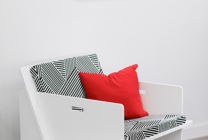
on the red side. Number 2, now I like a big chair and with
pillows added on all sides, it could be a really cozy look. With all the tiny
holes on its surface, I wanted to have a
decorative chair that will not be
covered in pillows. I took the advice Alex gave me to make the chair
a little narrower because with 62
centimeters between the armrest or 24.4 inch, it seemed like he was above
the average of an armchair. It felt more like a love chair. Number 3, because
it is so low on the ground and some of the
holes will not be seen, I decided to thin out the number of the hole
towards the ground, allowing the machine to
have a lower drilling time. Cutting time is very
important because if the machine takes a long
time to cut a chair, say 3-4 hours, because you design
little holes everywhere, then you can't produce that
many chairs during one day. You can only make two chairs a day so you can get
more machines and more people and rent
a bigger place or you make a more economically
insane decision, which is to modify the
design and have less holes. Depending on how many of these chairs you
want to produce, the cutting time can be a major decision factor
in the design. Number 4. Alex mentioned that now that the holes would not go through, the holes from the seating area would gather dirt or dust, so I remove them entirely
from this piece. Number 5. I also
decided to change the colors since the red I had chosen this time was too dark. Prepare to make these changes. We move to the cutting
of our final design.
17. The Final Prototype: For the final cutting, we use the board that could fit both chairs without leaving
a lot of leftover material, and that is 187 by
252 centimeters, which means 73.62 by 99.21 inch. First, the board
had to be painted and we painted it
on one side white, and the other one red. The paint we used is the water-based paint
we used before. But if you can find one
that is not water-based, I recommend you trying it because this one curved
the board a little bit. We wanted to change the
paint with one that is not water-based in the hopes that
the board would not curve. But unfortunately, the
store that was close by had limited choices on paints and weaker
water-based paint again. However, I did change the color from dark
red to passion red, which I find looked much better. The board was painted
with two layers of coating then it was polished and painted one more time with the same type of paint
we used on Test 2. As a designer, I took
the list of changes from the previous lesson and I
started implementing them. To have an overall understanding
on how things look, you need to make a copy
of the chair components. You modify the components
placed on the shape of the board and observe
the changes made in 3D. That way, when you modify the
components that are flat, you have a real view of how the overall design
of the chair changes. The first thing I
wanted to change is to make the distance between the two armrest 55
centimeters with 21.65 inch. Which means I have to
reduce the overall width of the backrest and seat
by seven centimeters, but the idea of the design was that all the parts
were equally wide, giving the chair this
overall cute-like look, so I reduced the size of
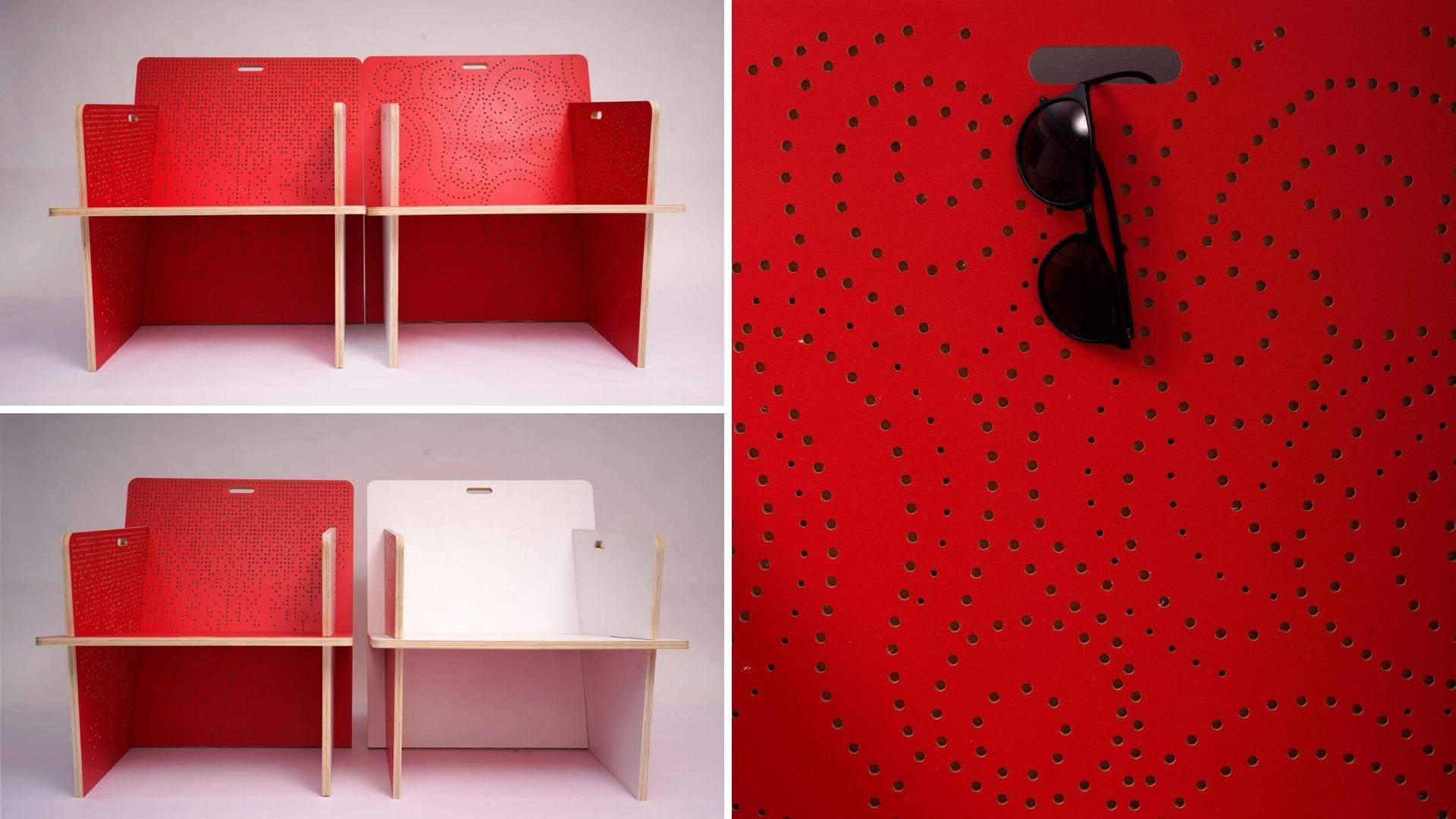
the two armrests as well. Let's have a look at our chair. It looks better
proportioned and closer to the size of a
standard armchair, which if we look in no effort is about 55 centimeters
with 21.65 inch. Not that my chair
components are smaller, I also want to modify the
decorative pattern on them. First of all, my pattern is dripping outside the
contour of the components, so that doesn't work. Secondly, because the chair
is so close to the ground, it doesn't make sense
to make the holes over the entire surface because they will be missed by
the eye anyway. Additionally, they can make the chair more
fragile as a whole, eroding its resistant
to pressure, so I decided to
make less holes and smaller holes towards
the base area. When it comes to
the floral pattern, I deleted many of the
six-millimeter holes towards the ground and added a few
rows in four millimeters. The overall impression is
that of a blooming tree with its trunk at the base and
thousands of blooms at the end. Also, I removed all
holes from the seat. Finally, I changed the big
hole at the upper side of each component with
a flatter grip hole. That will be more intuitive
for the user to understand, and the component can be
grabbed from the middle. This will make the
handling of the boards easier overall as
they are quite heavy. Because we made the decision
to drill only halfway, we first made the test to look at the depths of the holes. Here we have the
first test piece. The numbers over the holes are the depths of the
holes in millimeter. Three-millimeter,
five-millimeter, all the way to 50 millimeters, why are they important? First, it can be a design
choice to make a deeper hole. A deeper hole would leave a bigger shadow and
a superficial hole, and this will create an
overall graphical look. I absolutely follow about making more superficial
holes at the base of the armrest and deeper
ones at the top, but this would have extended the preparation
and cutting time. I was not sure it was worth it at the size of holes I have, so I decided to drop this idea, but it's definitely
worth to think about it. Finally, the board was
mounted on the table. As you can see, despite the vacuum sac, there are still some small holes between the board and
the cutting table. Nonetheless, after
fixing the board with additional screws on the cutting table and calibrating
the exact zero-point, the machine started
cutting from inside out. First, the machine cut the
four-millimeter holes, which took 17 minutes. Then the six-millimeter
holes followed, which took a lot more, and those took two
hours and 13 minutes. Finally, the cutting
of the components was done by tracing the
shape two times, and that took 38 minutes. The overall cutting time is
three hours and 13 minutes, which is not real at all. If you think about the time it takes to prepare the board, making the test, it's almost a day's work
of a human being, to focus only on this project. Now that we have all the
components of the final chair, we should put them together and have a look at what we made.
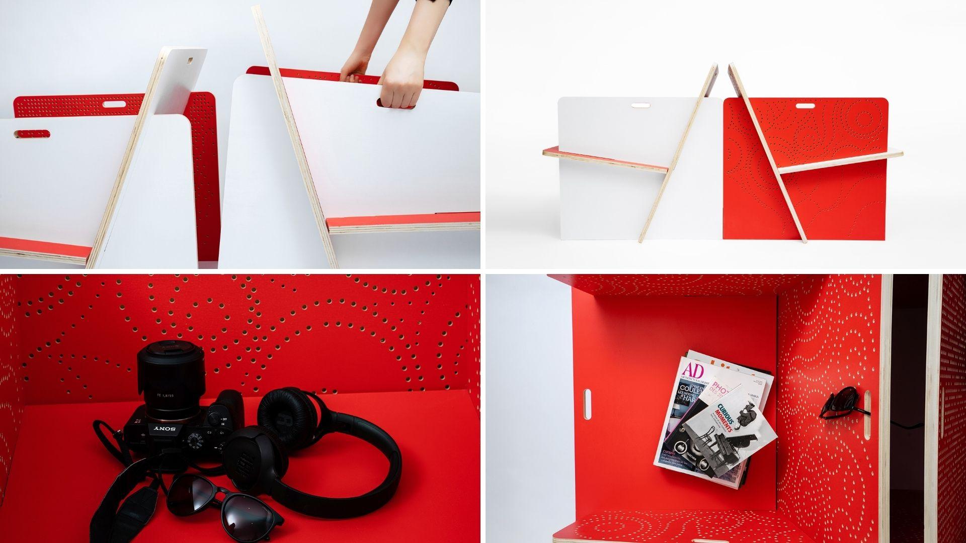
18. Assembly: Now that we have everything cut, the exciting part begins. We remove the component of the cutting board and
join them together. This is an exciting moment
for every designer. I felt like the master seeing Frankenstein rising
off the table, the moment of absolute joy. Before putting the
pieces together, we had to do a bit
of tidying up. First, we had to get rid of all the sowdust generated
in the milling process. After cleaning the table, the pieces were wiped clean, sprayed with an air
hose to make sure that even the smaller particles lingering in the holes
would be removed. Afterwards, the
edges were sanded lightly to get rid of
any splinters that have appeared just to make the manipulation
process more secure. After the thorough
process of cleaning, the assembly can take place. For the safe assembly of the chair more than one
person is required, ideally two, but the
assembly is done in no time. Let's have a look at the
Alex and his colleague. Also Alex, piece
the items together. The interesting part
about this chair is that you can change the
direction of its faces. You can have both the red and the white color
on the inside. For this assembly, we
decided to make one chair red on the inside and the
other one white on the inside. The grip detail proved
to be very useful too because now you can just lift a chair and move
it somewhere else. One of the grips had some
of the paint peeled off, which was a big disappointment. The distance between
the cutting board and a table must have been
bigger on that area. The other thing I looked
at was the joint. While the components came
together nicely Alex said he did not have the proper tools to
cut them at an angle, so they remained like this. I talked more about these
aspects in Lesson 11, customization
joints and corners. I also wanted to see
how they look in human scale and how
comfortable they felt, so I asked the two
Alex to have a seat. Here, you see how
tall the arm rest are and how far away from their
bodies they're located. I also wanted to feel how
comfortable they felt, so eventually I also had a seat. Here are some more
angles where you can see how the
chair looks like. They are quite a sight
because before they were planner 2D and now they are 3D, so don't be afraid to
take a couple of minutes, walk around them, test them, sit on them, see
how they feel and where the design might
need more improvements.
19. Further Improvements: Although the design of
the chair looks great, I believe that we
had just begun with product development
and this design could still be improved upon. If I could, here are the things I would improve
in the next prototype. Number 1, I would
definitely try to use more of the material and throw
away less from the board. As you know, sustainability
is important to me. If it actually helps the design, why not use a bit
more of the material? My first move is to make the arm rest and backrest
a little taller. Not a lot, enough to keep the
heights still comfortable. Number 2, I'd also look for a different
size plywood board. Perhaps there's one
that fits better, or might be cheaper if it
were bought in a bulk. The final board
we had to cut was about 140 Euros or $157, and this I paid without
a transportation costs. Just the material cost
of one chair is $78 in this without adding the transportation or the
manufacturing from Paola. Compare that with the fact
that you can pay as low as $5 for a chair at Ikea, makes this chair quite
unsuited for mass production. If making more was
ever an option, then finding a cheaper material
would be a top priority. Number 3, another changes
I would make is to make the holes or the
bits that I would like to cut out a little bigger, that way the drill could cut the material with its side
and not with its tip. It would be a clean cut, not a broken surface. The broken surface resulted
in the fact that the drill had to go straight through pushing the last
fiber of the wood. Number 4, I would find a way to have the joint cuts so
that the seat would fall flat on the backrest and the backrest would fall
flat on the ground. Either we would
find a way to cut the strange angles or I would
modify the inclination of the seat and that of the
backrest slightly to have them meet at an angle that will be easier to cut the
professional tools. Especially the lower edge of
the backrest is particularly difficult because if it is not resting perfectly
on the ground, it will probably crack
in time and gather dirt. Number 5. Finally, I
noticed that when I was sliding the components
in and out, traces of paint were showing
up on their surface. You would see either
white traces on the red surface or red paint
traces on the white sides. That is of course problematic. For my next design, I will try either to leave
it in natural colors. We'll look for a surface
that is more durable and less crunchy and less
likely to create traces. These are my five
improvement suggestions. With my chair finalized, I would like it to
be photographed professionally so I can
share it with the world. In the next lesson, I'm going to show
you what you need to focus on when
photographing your chair.
20. Photographing Your Chair: Once you have cut and
assembled your design, it's time to showcase it
properly by photographing it. I've asked my friend [inaudible] who is a professional
photographer, to take some photos
of the chair. He used a professional camera, a white background, and quite a few lights. I can't really go into the
details of how to take photos, but I would like to
explain what angles might be essential to
have in your portfolio. The 3D, that means that if
you have made a 3D object, show it in 3D. People have to understand how the parts connect and
how they hold together. You may have seen
industrial designers make drawings of their objects. They are always in 3D, so show at least two
sides. The colors. People love colors, and it's important to show the color versatility that
this chair has because I can change the phases
of the chair to be red on the inside or
white on the inside. I want to show this
with multiple shots how I can change the color
of the chair. The ensemble. If you make more than one item, then it would be
interesting to see how it relates with other
objects like it. This will help people have ideas about where your
design could fit. Maybe this chair could
sit on the terrors of a cafe or the venue area
of an office space. I also like the
geometry created with the backrest and seat
edges crossing them. It makes the entire look playful and graphical.
The patterns. Another thing that
is eye-catching is the decorative patterns. We put a lot of
effort into making the chair beautiful and unique
to show that to the world. You can have a chair
for frequent use, or maybe it can sit in
the corner of your home, display beautiful
objects like books, a camera gear, or perhaps a cat. It's always nice to have an image of how that
will look like. It also shows the scale and
proportion of your chair, your relationship with
other objects. The details. A specific detail that I have added to the chair is the grip because the individual
elements are quite heavy and
difficult to manipulate, so you want to showcase
those details and show how much easier to manipulate
the chair this makes. You can show the
stack of components, your hand on the group, and the rest happens
in the viewer's mind. Finally, your photos
need to have a vibe. I seriously try to give my
chair the playful spirit. Here are a couple of photos, more to display that.
21. Class Project: We're almost at the
end of this class, but I can't let you live without giving you
the assignment. That is to take the chair in the size and
dimensions in which Victor Papa Nick and
James Hennessy proposed it and customize
it to your liking. This chair is a blank slate
for you to play with. What I did to it is modified the distance
between the armrest, and with it, the width
of all components. I made the corners round, added a grip on all chair parts. I colored it on two sides and I gave them a
decorative pattern. For inspiration, I just
wanted to show you what other people on the Internet
did with the design. Here are a couple of examples. But you can do something
else entirely with it. You can modify it to
some of the parts. You can give it a
different color, or you color just the edges, or perhaps you can make a
beautiful hand painting on it. You can cut out parts of
the chair, and finally, you can also cut the chair with traditional carpentry tools if access to a CNC
milling machine is in some way restricted to you. The point of this class
is for you to feel empowered to make
your own furniture because once you start, you'll have this feeling of possibilities like you've
never seen before. I would like to
direct your attention to the project and
resources section where you'll find
everything you need to start making this
chair by yourself. These assets will be useful
to you in making 3D models, cardboard models,
or real prototypes. Share your process,
share your questions, and share your final
photos with me and your colleagues because they should be really interesting. Good luck with making the chair, and I'm looking forward
to your project.
22. Bloopers and Final Thoughts: Furniture design into reality. [FOREIGN] This course, of course is aimed at people who have some basic 3D
modeling skills. [FOREIGN] sound test. Hello and welcome to my class, design and build your own chair. [FOREIGN] [LAUGHTER] [FOREIGN] For this class, I have partnered
with my good friend, Alex Crystal from
FabLab Bucharest. Hey, good friend Anna.[LAUGHTER] I'm going to walk you
step-by-step through the entire design and
manufacturing process, showing you how to
harness [LAUGHTER]. [FOREIGN] Are you ready? Let's
start the class [FOREIGN] Congratulations, you have made it to the end of the class. I hope you learned
some new things and already feel
inspired to apply them. I enjoy teaching
this class a lot, and I can't wait to see what
you have taken away from it. I invite you to go to the Project and
Resources section and share your class project with me and other students
of the class. I'll make sure to give you feedback and help
you on your way. Do comment and encourage other students on
their class project. We will help you make some new connections on the platform. Please use the discussion
section to let me know your thoughts and
questions about the class. I'd love to help you clarify any concepts you
do not understand. It also helps me improve my classes so you
can learn better. If you enjoyed this class, I would appreciate a review. It tells Skillshare that
you liked my class and it encourages other people
to discover my work. Hit the follow button
if you want to see more classes like this one or follow me on social media
for weekly nuggets of architecture and design wisdom
or just funny thoughts.
 Ana Marcu, Home Wellbeing, Licensed architect