Transcripts
1. 00-01 Introduction: If you want to learn render and to the modeling from
the very basic, the new course is
exactly what you need. We'll start from zero, so no prior experience is
needed to take this course. The curriculum in this course
is carefully designed to help you learn vendor and do remodeling quickly and easily. After completing this
course, in Shala, you should feel very
familiar with vendor as if you have known the
software since forever. You'll have the
skill to model to the objects such
as these objects. In course, you will model this snowman character
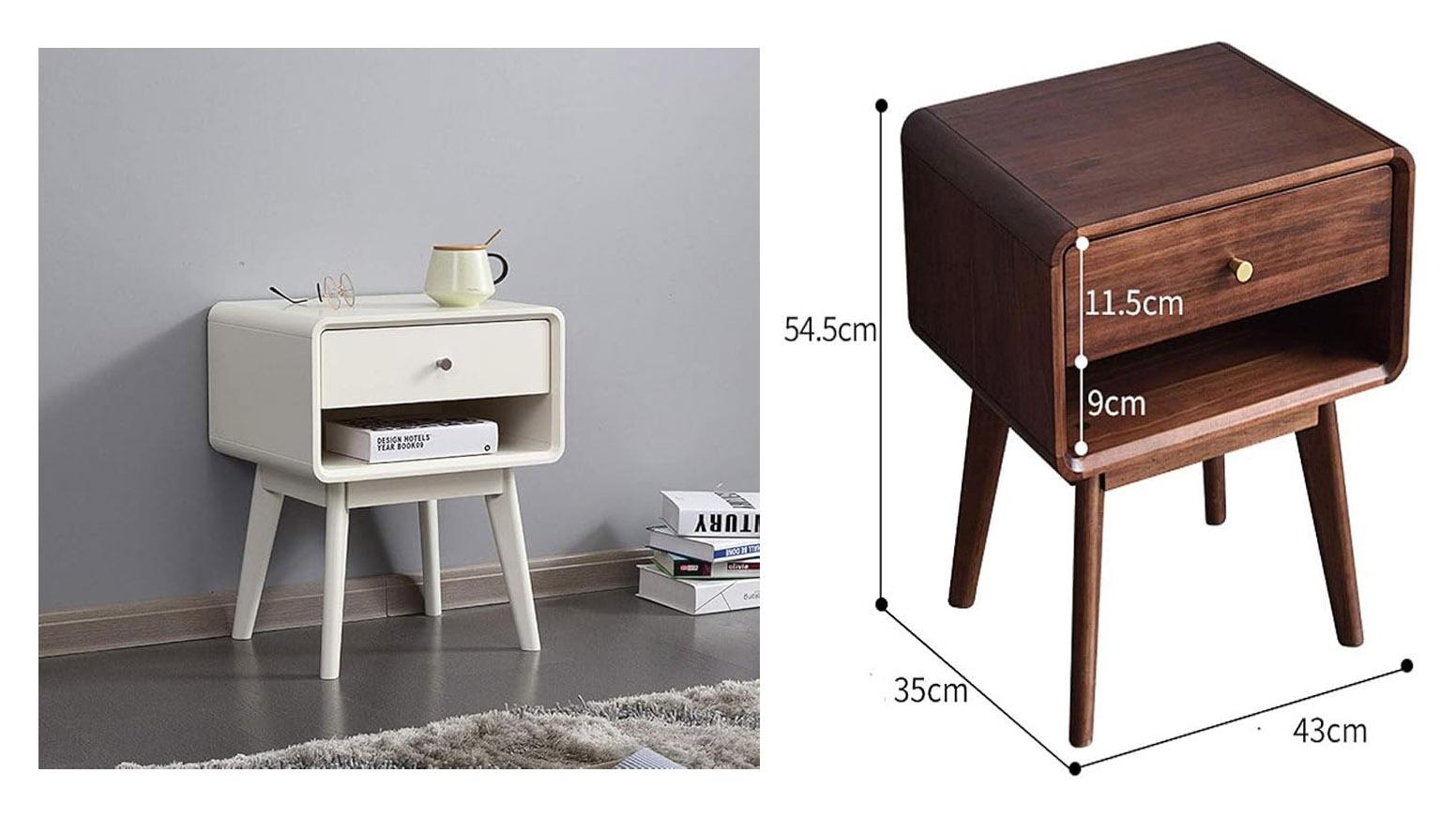
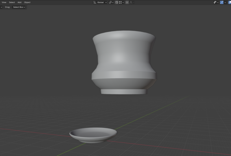
a simple side table, then a dining table, a window, a door with a knob, a classic style arch, a bowl, a vase. And finally, you will model this modern nightstand from a real world product reference. Salam Malako My name
is Wide Mutakin, founder of Expose Studio
for more than 20 years. I have created thousands of TD renderings like this
for architectural, interior and master
plan projects. I have worked with many
clients all over the world. I have clients on almost
every continent in the world. Besides doing
projects, I also teach three D and computer
graphics academically in several different schools
since the year 2000. In short, I have real world
professional expertise in tw D and experience
in teaching. So join now and take your first step into the
world of TD with Blender. Have fun learning Wala Malekum.
2. 00-02 Exercise files and conventions : Welcome to the course.
Before moving on, there are several things I need to mention and to
make clear first. This course is the first
course in a Blonder for essential series that
I published on Skillshare. In this first course, you will learn all the fundamentals, and then move on to
remodeling in depth. On the second course, you
will learn material creation, texturing, and new Vmpping
and on a third course. You will learn lighting, camera, rendering, and post processing using cycles rendering engine. While you can take
this course alone, I strongly recommend
that you also take the next two courses in
the correct sequence, so you have a
comprehensive reduce skill set in using Blender. You can download all the exercise files for
this course in the resources section of this lesson in case
there is a problem, as a backup, you can also download the files from
the following link. Please pay attention to the capitalization
of the letters, as this link is case sensitive. You can download the
files one by one, but it will be easier
if you just click this download button to download them all
in one zip file. The text you see here depends on where you are or your
language preference. It says, download Samoa
because I am in Indonesia. You will see the text
download all if you are in US or UK or English
speaking countries. As you can see, the
false nined based on lesson with additional
chapter code in front. Next, it's about the
structure of the course. I have carefully
crafted the curriculum so that everything is
placed sequentially. Each lesson you take on
one level will become the foundation of the
lessons in the next levels. Therefore, it is important
that you take the course in order step by step,
not jumping around. If you take the course
by jumping around, most likely you'll get
confused at some point. The second thing
I need to mention is that you need to practice. For each video, please try out the lesson yourself
at least once. The course is not
just about theories. Most of the lessons
are practical skills. So again, you need
to practice if you really want this online
course to benefit you. In this course, I'll be using a PC computer with a Windows
ten operating system. So every shortcut I mentioned in the video will be for
PC and Windows OS. If you are using a
Linux OS, most likely, you won't find any difference in terms of keyboard shortcuts. However, if you are a Mac user, you will find some differences. I believe most Mac users
already understand that the command key in Mac is often used to replace
the Control key in PC. And the option key in Mac is often used to replace
the key in PC. But the thing is about vendor. I found that most of the
control shortcuts in PC in Mac mostly become
this control key and not this command key, although there are some shortcuts
still use document key. Essentially, if you are
using a Mac computer, you may need to check the menu or the preferences window or the official vendor's
online documentation for the keyboard shortcuts. There are at least two
things that you need to have if you want to work
in vendor comfortably. First, you need a standard
mouse with a scroll wheel. Usually, if a mouse
has a scroll wheel, you can press on
the scroll wheel to activate the
middle mouse button. We will use the scroll wheel and also the middle mouse button
lot for viewport navigation. Want to avoid using minimalistic mouse
products that do not have any scroll
wheel or middle button. The second thing that you
need is a full size keyboard. What I mean by full size is that the keyboard should
have numpad area. This is important
because a lot of vendors navigation shortcuts are placed in the numpad area. Yes, there is an option in lender's preferences window
to simulate the numpad keys, but that will be at the cost of overriding other
important shortcuts related to TD modeling. So again, you really
want to invest in a decent full size keyboard if you want to use
bender for long term. Throughout the course, I may
display images and videos. Some of these contents
are not made by me. Please note that I am using them merely as references
or for inspiration. I never claim that these images
or videos are made by me. If I can find the owner's name, I will credit him or her by putting their names on
top of the content. Otherwise, I will
display image or video with the URA link
of where I found them. As for stock images or videos, if I don't specifically state
that they are made by me, most likely the copyrights belong to the respective
owners, okay?
3. 00-03 Vertex, edge, and face: In computer graphics, T objects can be represented
in many different ways. They can be measures, nerves, spline patches, Gaussian splats, point clouds, and so on. As technology evolves
in the future, we may see even more
methods to capture, store, and represent TD data. In its course, we will
learn the basics, so we will only
focus on the most common to the model
type, which is the mesh. This is the type of object
that you usually see in three D games and most digital
content creation software. A mesh TD object has
three types of elements. They are vertex, H, and phase. A vertex is essentially a
point in three D space. If we have more than one vertex, we call them vertoss. So vertex is a singular form, while ertosis is
the plural form. The second element is the edge. Edges are basically lines
connecting the vertices. So for an edge to exist, it needs at least two vertices. Having vertosis in edges is not enough to form
a visible surface. For this, we need the third
element called phases. In other three software, phases are also referred
to as polygons. So again, the terms phase and polygon are
basically the same. Phase is a surface formed
by connected loop edges. For a phase to exist, it needs at least three edges. You cannot have a pace if
you only have two edges. When a phase has three edges, we can also call it a triangle. When a phase has four edges, we can also call it a quad, and if a pace has
five or more edges, we can call it an angon you may be wondering what
is so special about pass with four edges
that we name them differently than phases
with five or more edges. We will discuss this leader in future lessons, but in short, using quad pass in
our model enables more modeling features compared to having triangles or angon. One state I need to
mention is that edges image type to the object
cannot bend or form a curve. This is quite different
compared to other types of the objects such as
nerves or spine patch. Essentially, in a
match to the object, if you want to form a
curve or round surface, you will need more
edges to simulate the curvature and automatically
more vertoss and faces. For example, a simple
cube model only needs eight vertoss 12 edges
and six faces to exist, while a sphere like
this one means dozens of vertssiges and phases. It does not matter if the cube is large and the
sphere is small. This sphere object
always requires more memory or
storage space than this cube object because it
contains a lot more elements.
4. 01-01 User Interface introduction: In this lesson video, we are going to explore
Blenders user interface. Blenders user interface is unique compared to other
software you have seen. Unlike other software,
the UI consists of multiple areas that can
be tileed as you wish. But before we get
into the details, let's talk about what the
default has to offer. When we start Blender
for the first time, we see this splash screen. You can close this
splash screen by simply clicking outside
the splash screen window. Now, if you're using vendor
on a public computer, such as in a
classroom or library, you may have different UILs
than what I have here. If that is the case, you may need to go to the
file menu up here. The faults, and then click on the factory settings button. Then click on the Road button. This will set everything
to the fault. This is important
so that we have the same starting point and avoid confusion
along the way. For now, there are only two things I want to
change regarding the UY. I need to do this so you guys can see the
lessons clearly. In the edit menu, there is a button to open the
preferences window. In a teams category, I change the preset from
blender dark to blender light. Personally, I prefer
the duck team because it is easier on
the eyes in the long run. But for teaching, I find that light colors are easier
for students to notice. The next thing I want to
change is the size of the UI. If we go to the interface step, you can see a perimeter
called resolution scale. One is the default value. I want to change it to 1.2 so that the buttons
and text look bigger. Again, you do not have to follow these two settings if
you don't want to. I'm doing this simply so you can see the
lesson more clearly. At least by now, you know where to find the settings if you ever need them. Finally, you can click on the Sef preferences button at the bottom to
save the changes. This is optional
because by default, all setting changes will be saved automatically
when we quit bender. But if bender or
Windows as crashes, or your computer's
power gets cut off, for example, you may
lose setting changes if you do not click the
sf preferences button manually right. Up here, we have the menu bar. In a file menu, you can perform file related operations
such as safe and open. Then we have the edit menu where we can perform
undo and redo. But most importantly,
this is where we can access the preferences window
as we just did earlier. Next, we have render
menu where we can render image and
render animation. Then we have the window menu where we can toggle blender
to full screen or not. We can also find the
new Window command, which is useful if you need to set up a multi monitor
working environment. After the menus, you can
see a lot of tabs up here. These tabs are
called workspaces. Essentially, in
ender, you can create your own or custom UI layout and save it as workspace
for convenience. This way, you can have different layouts
for different tasks. You can add Duplicate, delete and reorder these
workspaces as you like. By default, Blender already provides a lot of
workspaces to start with, such as layout, modeling, scoping, UV editing, and so on. We will discuss scene
and view layer leader. For now, let's focus on a fault or leftmost
workspace called layout. This large area in the
center where you can see a cube and grid thing is
called the T viewport editor, as the name suggests. This is where we can see our three objects from
different angles. At the bottom, we have the timeline editor where
we can play pose animation, set the visible starting and
ending frame, et cetera. This timeline editor will be very important if you
are doing animation. On the right side, you
can find two editors. The top one is called
the winery editor. This is where all objects in
the active scene are listed. You can select
objects hide them, show them, organize objects
using collections, et cetera. Last but not least is
the properties editor. This is where we set priameters whether they are global
parameters that affect the world and scene or contextual priameters
which affect only reselected or
reactive object. When working inside vendor, sometimes we want to escape from the UI complexity and just
focus only on one editor. You can maximize an
editor to take up the entire vendor window using a shortcut control space bar. But you must remember, and this is super important to know that all keyboard shortcuts in vendor work in conjunction with your
mouse cursor vocation. So for example, if you hover your mouse cursor over
the TD viewport editor, pressing Control Space bar will make that TD viewport
editor maximized. You can press Control Space bar again to toggle it back
to the original size. But notice if I hover my
mouse over the liner area, pressing Control Space bar here, we make the Oliner editor fill up the entire
vendor window. As before, you can press Control Space bar
again to minimize it. Again, I cannot
stress this enough. All blenders shortcuts work based on the editor where
your mouse cursor is located. Plus, you also need to realize that every
editor in vendor has their own set of shortcuts that may overlap
with other editors. Just to give you an example, if I try to rotate the cube in the TD viewport using
the R shortcut, everything works
exactly as expected because my mouse cursor is
on the TD viewport editor. But if I accidentally
place the mouse on the diner editor or on
the property editor, pressing R does nothing. But notice, if I position it on top of
the timeline editor, pressing R will bring up the
set key frame type menu. So if you ever try pressing
on a keyboard shortcut, but nothing happens,
you may want to check where you place
your mouse cursor.
5. 01-02 Editors and Areas: In this video, we
are going to discuss the editors in the areas of
Blenders user interface. If we look at the default
layout workspace, we actually have
four areas in UY, one, two, three, and four. In each of these areas, we can define what editor
we want to use or activate. Let's discuss how to work with the editors first and
then later the areas. At the time of this recording, there are a total of
23 editors in lender. This number may go up in the
future release of blender. Each of these editors is designed to tackle
a specific task. We already know the viewport
is used for viewing objects. The timeline is for
controlling animation. The outliner is for managing
objects in the form of list. And the properties editor is used for accessing the
object's parameters, we will cover other editors
when the time comes in shoo. Each editor always has an
element called the header. It is a horizontal strip with
buttons and or menus on it. By default, most headers are located at the top
this outliner editor, for example, this whole area
is the outliner editor, and the bar at the
top is its header. The same goes with the
properties editor. This whole area is the editor, while the bar on top
of it is its header. If you prefer the
header location to be at the bottom
of the editor, you can do so by Rod
clicking on leftmost icon, choose header, and then
choose flip to bottom. Personally, I prefer all
headers to be on top, so I am changing this back
to the top, all right. You may notice that the
T review port editor looks a bit different. It seems that it does
not have any header. Well, that is not true. It also has a header, but the header is transparent. You can also move this header to be the bottom if you want to. This depends on your
personal preference. Now, the reason why we need to discuss the header is because this is the area
where you can find the icon to switch
the active editor, which is the icon on the leftmost position
inside the header. As you can see, currently, there are a total of
23 editors in vendor. Just for example, let's
say we want to change the active editor of this area from the three viewport
into the Outliner editor. Just click on the liner option. And now this area displays the outliner editor
just like this area. If we click the top left icon again and then we
choose properties. Now this area displays the properties editor
just like this area. You can do this with all of
the areas in blenders y, such as making this
area a three viewport, for example, and so on. I'm sure you get the idea. Let's switch back these editors, so we have them as
when we started next, let's focus on
controlling the areas. If you notice there
are line gaps or black borders between
the UI areas in render. We can use these borders
to resize the areas. You will see the mouse cursor
change to an arrow symbol. Whenever we can click
and drag these borders, we can do this both on vertical borders and also on horizontal
borders, all right. Now, if you hover your mouse, not on the vertical no
horizontal borders, but instead on corners, the mouse cursor changed to a plus or sniper scope symbol, please be very careful
as in this condition, you will perform splitting or joining areas
when you click wag. The method that I'm about
to show you is quite hard. A leader, I will show
you easier method. So if you want to
skip this method and jump straight to the
easier one, that is okay. Let's say you want to split this area into two
areas top and bottom. To do that, first, you
need to make sure that the corner you are on belongs to this area, not this area. I know this is very subtle, but just make sure that the most cursor is on left
side of the vertical border, not right side of it. Then you need to click drag
downward into the area, so if you click drag it to
the left or horizontally, you are splitting the area vertically or left and
right instead, right? We can use this method
also to join areas. Let's say we want to join these two areas by
removing the right one. For this, you need to
hover the mouse cursor on a corner but slightly
to the left side, and then click drag and
move it to the right side. Blender will preview
the area that will be removed by making
it a bit darker. Release the mouse, and we just joined the two areas
above into one. The concept applies to
joining areas vertically. Let's say we want to join these two areas by
removing the top area. First, hover the mouse
cursor on this corner, but slightly below
the horizontal gap. Click drag it up and
then release the mouse. And we are now back with only one large area
at the center. I have been teaching
Bender for quite some time now at the university
and also in workshops. One common problem
that my students have is when they try
to split or join areas, they get the wrong results. Mostly, these problems
happen due to mistakenly dragging the wrong
corner point and also sometimes in
the wrong direction. So they end up with so many needless areas
in their UI layout. The bad news is
that splitting and joining areas are not part of the commands in vendor
that are undoable. In other words, if you make a mistake in this process,
you cannot undo it. If for some reason, you end up with a
messy workspace, it will be easier to just remove it and
recreate it again. To do that, right click
the workspace tab, and then choose the lead. Then to create a new one, you can click on
this Plus button. Just the name of the
workspace you want to create. In our case, it is
the layout workspace. Finally, to move the
workspace tab to the left, you can wild click on the tape again and then
choose the to front. All right. If you despise the corner rag
method, don't worry. You are not alone.
And the good news is Brander provides an
alternative method that is way easier to perform. Through this, you do not
need to access the corners. All you have to do is right
click on a border area. Let's say we want to split the three viewport
editor horizontally, simply right click
in this border area, and then choose
horizontal split, move the mouse cursor to define the location where the
split should happen. And then click to
confirm. Another example. Let's say we want to split
this top area vertically. You can just right
click on this border. Then choose vertical split. Define the location, and
then click to confirm. Besides splitting areas, you can also join areas
using this method. For example, we want to
join these two areas. You can right click on this
border, choose join areas. Then choose which of the
areas you want to remove. Click to confirm and
here is the result. We now have larger area from joining the
previous two areas.
6. 01-03 3D viewport navigation: In this video, we are going to learn how to navigate
the TD viewport. For most people, the
T viewport will be the editor where they do most
of their work in vendor. This is why it is
the first editor we need to cover
before anything else. When we start vendor
for the first time, we have a cube object
in the center. There is nothing
wrong with the cube, but we need something more
to tell us the direction. When we are practicing
navigation techniques, we will discuss object creation and transformation in
more detail either. For now, just make sure the cube is selected
by clicking on it. Activate the move tool. Then click drag the red arrow to move the cube a
little to the side, about two or three grids. Now, let's create a
monkey head model. We can use the menu
located in the header, then slack mesh, and then
select monkey, all right. To rotate the TD
viewport around, you can press and hold
the middle mouse button. If you are using a standard
mouse with a scroll wheel, you need to press
the scroll wheel down to activate the
middle mouse button. Now, you must remember
that we are not rotating the monkey head
or the cube objects, or objects in our
scene are unchanged. What we are doing
now is rotating our view or how we see the TD world inside
the TD viewport. Next, to zoom in and
out of the viewport, we can use the
most scroll wheel. So instead of pressing it down, we are now rotating
the scroll wheel, scroll up to zoom in and
scroll down to zoom out. Now, when zooming with
the scroll wheel, we get this stepped motion. If you don't want
this step effect and prefer a smooth zoom motion, you can use the
alternative method, which is by holding the Control key and then pressing the middle
mouse button. As you can see, the zooming
motion is no smooth. The next navigation method
is pinning the viewport. For this, you can hold the Shift key and then press
the middle mouse button. As you can see, as
we direct the mouse, the viewport will
move right, left, up and down relative to
our eyes or viewing angle. Sometimes we rotate
or zoom in or out too much in a TD viewport
and get lost in space. If this ever happens to you, you need to use one of
these focusing shortcuts. The first shortcut
is the home key. We use home to automatically frame all
the objects in the scene. So again, whenever you lose track of space in a TD viewport, just press the home key to
see all of the objects in SN. The second important
shortcut is the dot or the period key that
exists on a numpad. Remember, not the one in the middle area of the keyboard but the one on the numpad. This dot key will automatically frame the viewport to
the selected object. So of course, for this
shortcut to work, you must have at
least one object selected if nothing is selected, such as when we click
on an empty space, pressing the dot
key will do nothing because Blender does not
know where to focus. Okay, guys, those are the
basic techniques for nation. I strongly recommend
that you memorize and practice these techniques before moving on to the next lessons. There are three settings that
I always turned on to make viewport navigation in lender way easier and feel
more intuitive. These settings are optional, but at least I want you to try them for now and see
if you like them. You can always turn them off later if you
don't like them. To access these settings, you can open the edit menu and then open the
preferences window. Next, open the navigation tab. You want to turn on
this orbit around selection dab and Zoom to most position check
boxes a quick explanation. The orbit around selection
option will make the viewport use
the selected object as the center of the
viewport rotation. This way, we won't lose focus from the object we
are currently working on. The depth option will
make bender respect the depth of the surface where the mouse cursor is located. This option will affect
all instigation processes, whether it is rotating,
zooming or panning. And finally, the Zoom to mouse position option will make the zooming process respect
the mouse cursor location. If you are done, you can
close the preferences window by pressing the
top left X button. The settings will be saved automatically we need
a liquid bender. Although using mouse
is the fastest way and my preferred method of
navigating the TD viewport, sometimes we are forced
to use other methods. Perhaps our mouse is broken, or maybe we accidentally
left it somewhere else. There are two alternative
methods that we are going to cover the
buttons in the UY, and then the number
keys on the keyboard. Since Benner version 2.8, we have several UI
elements in a TD viewport that we can
use for navigation. Let's start with the
viewpod rotation. To rotate the viewport, we can hover our mouse cursor to this area that has
small colorful circles, and then just click
and drag around. When we do this, the mouse
cursor becomes hidden and viewport will rotate around following
our mouse movement. If we release it, the mouse
cursor will be back at the exact location where we
start dragging. All right. Next to zoom in and
out of the viewport, we can hover our mouse on top of this magnifying glass icon
and then drag it up and down, drag up to zoom closer and drag down
to zoom further away. The last technique is panning. For this, we can click
and drag the hand icon. The viewport will pan around according to our mouse movement. So these are the navigation
techniques utilizing the UI. The last alternative method is by using the numbered
keys on the keyboard. To rotate the viewport, you can use the keys number two, four, six and eight. Number two and number eight are for rotating the
viewport vertically. Number four and number six are for rotating the
viewport horizontally. For zooming in and
out of the viewport, we can use the plus and the minus keys plus to zoom
in and minus to zoom out. And finally, to
pen the viewport, we can hold the
Control key and then press the number four
or number six keys. This will pen the
viewport horizontally. If we hold the
Control key and then press the number two
or number eight keys, this will pen the viewport
rotically so that is how you can perform viewport navigation
using only the keyboard.
7. 01-04 Orientation Convention and Axis Viewpoints: In this lesson video, we are going to discuss the orientation
convention and in later how to activate
the axis viewpoints. Unlike two D, where we only
have two axes, X and Y, three D objects or three
D scenes have three axes, X, Y, and Z. In render, each of these axes can be
positive or negative. This is the positive Xaxis, which is this way, and this is a negative X axis,
which is this way. This is the positive X axis. This is the negative X axis. This is the positive Y axis. And finally, this is
the negative Y axis. Now, you need to realize that different D software may have different
orientation conventions. For example, what is considered to be the
up direction into theSMx is different from the up direction in Unity
game engine into the SMAx, the updirection is the
Zaxis just like in Blender. But in Unity, the updirection is the Y axis, as
you can imagine, it can be a bit daunting if you have to work
back and forth between multiple to the software that have different
orientation conventions. But there is at least
one thing that is common or uniform across all the
software in the world, and that is the
colors of the axis. No matter what software
you are using, the Z axis is always blue, the Y axis is always green, and the X axis is
always red, right. For now, let's focus on the orientation
convention inside bender. To help us visualize
orientation, we can create a
monkey head model just like in the previous resin. So in Dender the up direction
is the positive Z axis, and the down direction
is the negative Z axis. And then the front direction
is the negative Y axis, while the direction is
the positive Y axis. As you can see, the monkey head is facing the negative Y axis, not the positive Y axis. This explains why this middle
grid line is colored green. That is because it shows
the direction of DY axis. Now it's a bit tricky to discuss the right
and left direction. If you base orientation
onto the object, this should be the
right direction or the negative X axis, and this should be
the left direction or the positive X axis. However, Blender and
many other software do not base the left
and right directions on to the objects, but instead on the
user's point of view. So this direction is the right direction or
the positive X axis. While this direction is the left direction or
the negative X axis. This is something you
need to keep in mind. After you understand the orientation
convention in vendor, whenever you create a
new TD model in vendor, you should always try to make it pace the front view or
the negative Y axis. Why? Because, leader, when we view the object
from the front view, it is the front side of the object that we are looking
at, not the other side. Another reason for this
is also the default setting for mirroring in
vendor is using the X axis. Yes, you are free to
change the settings, but having our object facing the default from
direction can prevent us from confusion and from extra steps in twaking the
parameters or settings. All right. Next, let's discuss how to use or activate
the axis viewpoints. Basically, access viewpoints are special viewing presets
where we can see our scenes straight
from certain axes we often refer to these
views as front view, side view, top view, and so on. There are three methods
that we can use in vendor to access the
axis viewpoints. The first is using the UI
or these colored axis. The second is using keyboard
shortcuts and finally, using the mouse and
keyboard combination. As discussed the
UI method first, to access the front view, you can click on the green
circle that says minus Y. As you can see here, we are now in the front
orthographic view. You press the positive y circle, we are now in the
back orthographic or the opposite of
the front view. If you are wondering orthographic
means that the view is straight or into the mode or does not use any
prospective effect. If for some reason, you want to see the front view, but in prospective mode, you can press this icon. This will force the view to be displayed in
prospective mode. Click again on this icon to go back to the
orthographic mode. To go back to the standard
or non axis viewpoints, simply rotate the
viewport using the mouse or using the access
circle again by default, vendor will turn on
the prospective effect whenever it detects
non access viewpoints. All right? To access the
other access viewpoints, the method is
basically the same. You can click on a
positive Ecircle to activate the right
orthographic viewpoint. Rotate the viewport to go
back to the standard view. Click on the positive
Z circle to activate the top viewpoint and rotate the viewpod to go back to the
standard view, and so on. I am sure you get the idea. The next method is by using
the keyboard shortcuts. For this, you need to
use the numpad area. First, it's the number
one key in the numpad. This will activate the
front orthographic view. Then the number three will activate the right
orthographic view. Last but not least, it's the number seven key, which will activate the
top orthographic view. So those are the
three keys in the numped that you can use to
access the axis viewpoints. Now, you might be thinking, why in the world did
Bender choose numbers one, three, and seven for switching
the axis viewpoints? Well, to help you
memorize the shortcuts, just imagine this
drawing in your head. When we were in high school, we learned how to draw simple, technical drawings on paper. Let's say we want to draw a car. Usually, we need to start
with the front view. Then we take our
ruler and create these guidelines so we can
draw the top area precisely. And we create
horizontal lines like this to guide us to draw
the car from the side view. Okay? So this is the front view. This is the top view, and
this is the side view. Now, if you map this
image to the numbed area, the number seven key position
is at the left top corner, just like this top view drawing. The number one key is for the front view located at
the left bottom corner, just like the car's front view, and last one is the
number three key located at the right bottom
part of the num ped, exactly like the position
of the cars side view. So again, by imagining this
image or layout in your head, you should remember the
shortcuts much easier. Now, you may also wonder, can we only see three
axis viewpoints using the keyboard shortcuts? What about the B view, bottom view, and left view? Can we access them also? The answer is yes, there are two methods
to access them with the help of the control
key or using the nine key. For example, if you want to see the bottom view because the bottom is the
opposite of the top view, we can hold Control and then
press the number seven key. Now we are on the bottom view. To see from the left view, you can hold Control and then
press the number three key. And finally, to
see the back view, you can hold Control
and then press the number one key. All right. So this is the first method. The second method is by
using the number nine key. This key is used
to flip the view. So for example, if we want
to see the bottom view, we can press seven force, which essentially turns
the view to the top view. In this condition,
if we press nine, the view port will flip. So now we are seeing
from the bottom view. To see from the left view, we can press three first
and then followed by nine, to see the back view, we can press one first and
then followed by nine. Okay? The last keyboard shortcut I want to mention
is number five. Pressing number five
in the numpad is like pressing the prospective
togo icon in the UI. Pressing it once will activate
the prospective mode, and pressing it again, will activate your orthographic mode. So that is how you use the keyboard shortcuts to
access the axis viewpoints. The last method that we are
going to discuss is using the mouse and
keyboard combination to access the access viewpoints. Basically, if we press the key while performing viewpoint
rotation with the mouse, vendor will automatically snap the view to the nearest
access viewpoints. And if we are already
in an axis viewpoint, such as the front view, holding out and middle mouse dragging the
view to the left, we activate the right view. If we do that again, we
will be in the back view. And if we do it again, we are in the left view, and again, we are back
to the front view. Now, if we hold out and then use the middle
mouse to drag down, we will be in the top view. And if we rotate the view without holding any
key on the keyboard, we are back in a standard
perspective view.
8. 01-05 The 3D cursor: In this lesson video, we are going to discuss the treaty cursor
feature in Blender. If you want to follow along, I already prepared this file
that you can use right away. You are also free to use your
own file if you want to. So what exactly is
a treaty cursor? Well, if you look closely at the center of the
treat world in bender, there is a small circle that looks like a sniperscope target. This is the Tretcursor. It is basically a pointer in treD space that can be used for a lot of
things in dender. One of which is for refining the location of newly
created objects. So again, this is something
you need to keep in mind. Every time you
create a new object, Blender will place that object at the location of
the T D cursor. By default, the three D cursor is located at the
center of the world. We can move or position it to any place we want using
one of these four methods. The first is by holding the shave and then we
clicking or right click g. Blender will detect
the surface at the most cursor
location and then place the TD cursor
on the surface. The second method is to activate the cursor tool in a tool panel. If somehow you cannot
see the tool panel, you can use the
letter T shortcut in the keyboard to show
it or to hide it. Again, you need to make sure your mouse cursor is inside
the three D viewport. If your mouse cursor is on
the other area or editor, the shortcut won't work. All right. So with
this tool active, you can click or click
Greg anywhere in the scene to reposition
the three cursor. Now, I know we haven't
discussed snapping, but just to give you an insight, you can use the first
and second method along with the snapping feature
with the snap mode turned on, you can easily snap the
tree cursor to vertices, edges, fishes, et cetera. Let me turn this off again. We'll discuss snapping
reader in a separate video. Okay? The next method is by
using the snap commands. This is different from the snap feature I just showed you. To access the snap commands, you can either go
to the object menu in a header and then use snap, you can see these
commands that can help you snap the tree cursor
to certain things. A faster way to access the
snap commands is by using the shortcut Chief as you can see and access
all the snap commands, but in the form of a Pi menu, you can right click to
cancel the Pi menu. Just to give you an example, let's say you want to move the T D cursor exactly at
the location of this sphere. First, we need to select
the sphere object. For this, you can use the Select tool or any of
these transformation tools. Then click on sphere
object to select it. In this condition, we can
brass shift as to open the snap by menu and then
chooe cursor to select it. As you can see, the T Dcursor is now at the center of
the sphere object. The fourth method of positioning the Tcursor is via
the side panel. To expand and
collapse this panel, you can press letter
N on keyboard, so press N to show it, and press and again to hide it. If you open a View tab
in the side panel, you will see a section
called trite cursor. If you cannot see
the parameters, make sure the section is expanded by clicking on
the name of the section. This is the section
where you can access the coordinate values of the TD cursor along with
its rotation values. To change the three
D cursor location, you can type in a
number manually or you can click drag in any of these fields to
change its value. Please note that
you can do this on any numerical input fields
in vendor. All right. Now, if you want to
reset the location of the Tre de cursor back to
the center of the world, you can click drag Lo to select all the
coordinate input fields. If you type in zero, all of the fields
will have zero value, which basically sets
the location of the td cursor to the
center of the world. You can do this also with the rotation values if you want. However, there is
a quicker method to center the three D cursor, and that is by
using the shortcut Shift C. With this shortcut, not only is the three
D cursor centered, but blender also moves the viewport to the
center of the world. Now, if you press Shift
for the Snappy menu, you can also find a
command for centering the cursor called the
cursor to world origin, but it will be faster if
you just press Shift C.
9. 01-06 Creating and deleting objects: In this lesson video, we are going to discuss how to create new objects in lender, how to tweak their parameters, and then later learn
how to delete them. To create a new object, first, we need to specify
where the object will be created by positioning
the tree recursor. For example, if you want to create a new object at
the center of the world, but the tree recursor
is somewhere else, you can press Shift
C to center it. But if you want to create the object on a certain
location or surface, just hold Shift and then
right click on that location. Next, to add a new object, you can use the shortcut **** A. This is a very
important shortcut, so I suggest that
you memorize it. Notice that you get the
same list of commands as when you click the Ad menu
in a viewport header area. If you notice, lender provides
many types of objects. In its course, we
will be using and dealing with the mesh type
object most of the time. The mesh type is the basic to
the object used in lender. It consists of vertss,
edges, and pass. It is the same type
of object commonly used in other to the
software and game engines. We have created a
monkey head before. So let's try creating another
object, say, a cylinder. Now, please do not do
anything else yet. Every time you create
a new object in ender, you can access all
its parameters via this small menu at the left bottom area
of the TD viewport. In this panel, you can define the number of vertices
around the cylinder. The more vertices
the cylinder has, the smoother the side area is. But of course, at the cost of
larger memory requirements, the rule is that
you always want to use as few vertices as possible that you can get away with if the object is small or
far away from the camera, there is no point in adding a lot of vertices to the model. But if the model is big and
very close to the camera, you may want to have more
vertices on the model, so it does not look
jagged, right. You can play around with
the other parameters to find out what they do. Sometimes you need to see the wireframe to
support the changes. For example, we can
tell the difference between the nothing option
and the ngonoption. Nothing will basically remove the top and bottom cap faces
from the cylinder object. But to see the
difference between the Ngonoption versus the
triangle of an option, you need to turn on
the wireframe overlay. To do that, you need to click on small carrot button
of the overlay icon, which is the third
from the left. Then in the geometric group, there is a checkbox
that says Wireframe. Click on it, and now you can see the wireframe or the structure that makes up the mesh objects. If you want to hide it, simply
click on a checkbox again. For now, let's
have it turned on. If we go back to the
cylinder parameters, we can now tell the
difference between the engon and
triangle in options. Okay? Now, this is very, very important for
you to remember. This panel only shows
up once in a lifetime. That is, only the first
time you create a cylinder. After that, you cannot
access these primeters again as the cylinder
becomes an editable object. If you click on an empty space, for example, the
panel disappears. If this ever happens to you and you still want
to edit the parameters, provided that you haven't done anything else other than
distracting the cylinder, you can still access
the priameters by pressing the
shortcut of nine. With this 14 panel, you can tweak the cylinder's
primeters just like before. But if you do something
else after this, such as moving an object, deleting an object, copy
pasting, and the like, you won't be able to access the parameters again,
the panel on the left. Now, this place dress
action that we just did, so we can revise it if needed. So that is basically
how you create a new object in lender and
how to tweak its primeters. I know we only discuss
the cylinder object. However, the concept or workflow is the same for the
other types of objects. So feel free to experiment with the other object
that vendor provides. There are at least four
methods that you can use in vendor to delete
an object or objects. But the w flow is identical in which you need to
select the object first, only then you can delete it. Let's say we want to
delete this object, we need to select it
first by clicking on it. Then press either the delete
key or the X letter key. If you use the delete key, Blender will just delete the object without
confirming your action. But if you use the X letter key, Blender will try to
confirm your action first. Let me undo this. Another way to delete an object is via the
contextual menu. Again, you also still need to select the object first
by clicking on it. After that, you can
right click to open the contextual menu
and then choose led. Thes method is by using the outliner to select
and delete objects. You can select an
object by clicking on its name in the
Outliner editor, and then after that, you
can press X or press Delete or right click on the
object and then choose led. Now, you may be wondering, what if we want to delete
multiple objects at once? Well, you need to
select them first and then do one of the four
methods we just discussed. We will have a
dedicated lesson video on how to select
objects in ender. For now, you can
hold Shift and keep clicking on objects if you
want to select them all. After we have all the
objects we want to remove, selected, we can
press the delete key. If you want to use a click Breck method to
select multiple objects, you need to make sure first that the select tool is in
a select Box mode. If this is active, even
if you are in Move tool, clicking and
dragging will create a selection bonding box that
can select multiple objects, and then you can press X
or delete to delete them. The same concept applies
to the outliner editor. You can click drag to create a selection bonding box that can select multiple
objects at once, or you can use the Shift key and or the
Control key to select them. Just like in
FaxplorerHlding Shift will select items
continuously or in range. While holding Control can help us select multiple
objects randomly. After that, you can press X, press Delete or white
Cl, and then delete.
10. 01-07 Object selection basics: In this lesson video, we are going to discuss how
to do basic object selection in lender and then later learn
about the selection tools. First, let's recap what we have learned so far in terms
of object selection. We already know that we can click on an object to select it. We also have discussed that we can hold the
shift key and just keep clicking to select
multiple objects. All right. Now, let's discuss how to select and select all
objects in the scene. To select all objects
in the scene, you can press letter
A on the keyboard. To disselect all objects, there are three methods
that you can use. The first method is by clicking on an empty space in a viewport. We have discussed this
technique briefly before. The second method is by
pressing out a shortcut. Third method is
quite interesting. In Lander, you can select all objects using
the same shortcut as selecting all objects, that is using letter A, but you need to press
it twice quickly. So if you press A once, all objects get selected. But if we press A twice quickly, none of the objects
will be selected. Many users prefer this double
A method instead of the out a method because you don't need to use another finger
to hold the outkey. Last technique I want to mention is inverting
the selection. For this, you can use
the shortcut Control I. So let's say we
have these objects selected by pressing Control I. Now, they are not
selected anymore. Instead, the other
objects that were previously not selected
are now selected. All right, I suggest
that you memorize all these shortcuts as you will often need them when
working inside vendor. If you ever forget
the shortcuts, just click on the select
menu in a viewport header. You can see the commands and
their shortcuts up here. Next, let's discuss
the selection tools. It is very important to
realize that in vender, object selection behavior works based on the active
selection tool. If you click and hold
the Select tool, you can see that vendor provides four different
variants of it. If you prefer the shortcut, you can use the WK to access the selection tool and
switch between its variants. The way the shortcut
works is like this, Let's say you have
the move to active. In this condition, if
you press the WU once, the select tool
will be activated. Then if the select tool
is already active, pressing the WU again we cycle the selection
tool variance. Let's discuss each of
these variants one by one. The first variant we need to
discuss is the select box. This is the default
selection tool when we first open vender. Basically, when the
select box is active, we can create a rectangular
selection region by clicking and ragging
in the viewport. Notice that every time
we click and drag, a new selection is created, canceling the
previous selection. If you want to add more
objects to the selection, you can hold Shift
while click dragging. With this, Blender will
not create the selection, but rather select
new objects while keeping the previous
objects still selected. If you want the reverse
behavior, that is, if you want to sub track objects from the previous selection, you can hold Control and then click drag to create
the selection region. Objects that are touched by the selection region
will be deselected. A more advanced method, but rarely used one is
intersecting the selection. For this, you need to hold down both the shift and control keys together and then quick drag to create the
selection region. This method, Blender
will only keep the selected objects if they
are previously selected. So again, to recap, you can hold shift to add more
objects to the selection, hold control to
subtract objects from the selection and hold Shift and control together to
intersect the selection. If you ever forget
the shortcuts, you can also use
these small icons on top to activate the modes. This is the default mode, which will replace
the selection. This is the add mode or so
called the extent mode. This is the subtract mode. And this is the intersect mode. By using the icons, you can also access the
inverse introsection mode. This is like the intersection
mode but in reverse. All right. The next selection tool
variant is the twig tool. This tool is actually not
just a selection tool. It is a combination of the selection and
move tools in one go. This tool is super useful if you want to make a lot
of small changes to the objects positions
quickly rather than switching between
the select tool and then move tool
back and forth, you can click and drag objects quickly to position
them using this tool. Please note that these
are almost all tools in blender works based on
the active viewing angle. So if you want to
tweak object positions only on the X and Y plane
and not on the Z axis, then you should perform
tweaking from the top view. This way, you can be sure that the objects we
move around will not be changed in terms of their
z coordinates. All right. The next section to variant
is the Strack circle tool. This variant will change
the mouse cursor to circle, and the way we strike objects is no like a plain brush
tool in rolling software. You can change the brush size by changing this radius value. Now, you need to remember that the select circle
tool only selects objects if the origins of those objects are touched
by the circle cursor. If you wonder what
the origins are, they are essentially the
center of every object indicated by a noticeable
yellow or orange point. We will discuss objects origins in more depth
in later video. For now, just make sure you
move the circle crousor deep enough so that the center of the object is touched by it. Otherwise, it will
not get selected. Okay, like the select box tool, you can hold Shift to add
more to the selection, and you can hold Control to subtract from the
previous selection. You can also use these icons
to activate the modes. Notice that the Slack
circle tool does not support intersection or
reverse intersection modes. The last section tool variant
is the select lasso tool. This tool is very useful
when we need to select certain objects in a very
intricate space or environment. Essentially, with this tool, we can roll a
custom section area by clicking and
wagging in viewport, just like the
Select circle tool. This tool also works based on the objects origin location so if you try to draw
a selection region, but it does not include
the origin location, the object you want to target
will not get selected. You may already
notice that this tool has all the modes that
the select box tool has. So with this tool, you can make use of the shift
key to add more selection. Use the Control key to
suprat the selection and use both the shift and Control keys together to intersect
the selection. Alright. As I mentioned earlier, Blender will use the
active selection tool as the default
selection behavior. That is, when you perform
click dragging while you are using any of the
transformation tools, we will discuss transformation
in more depth leader. But just to give you an example, if you have the
Select Lasso tool active and you are
in the move tool, if you try to click drag on a
viewport to select objects, instead of creating a
rectangular selection region, you are creating a custom
shaped selection region. Another example, if you activate the Select circle tool and we are now in
the move tool again, click rating on a viewport will trigger the circle
selection method, not the rectangular
selection region. Now, there are ways to
activate different types of selection techniques regardless of reactive selection tools, but that will be a discussion
for another video.
11. 01-08 Basic viewport shading modes: In Elasson video, we
are going to discuss different types of port sharing
modes available in ender. Because leader, we will deal
with viewport rendering. You want to make sure that you use all your
computers potential. For that, you need to go
to the preferences window. In a system tab in the top area, you can see the cycles
render devices. If this is set to none, while you have OS GPU
or graphic cards, you are wasting a lot of
your computer potential. So how can we set
this correctly then? Well, if you have an
RTX graphics card, you should always activate
the Optics option and then turn on the checkbox that belongs to your
RTX graphics card. This is currently the fastest rendering technology
available in vendor. At least by the time
I recorded the video. If you have older and
video graphics cards, such as the GTx family, you want to use the Cod option. If you use AMD graphics cards, such as radiant family, you should use the hip option. If you use intel graphics cards, then you should use
the one API option. And if you are in
the Apple ecosystem, you should use the metal option. Unfortunately, the metal
option does not show in my computer as I'm using a PC with a Windows
operating system, but you should see
the metal option if you're using my computer. Okay? Notice that my CPO, which is an AMD processor, actually supports Optics, but I deliberately
turn the option off. This way when vendering
vendor only uses the GPO. This makes the CPO free to do other stuff that my
computer requires, such as running the screen recording software
in the background, which also demands a considerable amount of
computer performance. If you have CPU and you don't have anything else running in the background, you may want to turn this
checkbox on all right. The TD viewport editor in render supports four
different shading modes. They are wireframe, solid material preview,
and render preview. You can quickly switch
between them using these small icons at the top right location
of the TD viewport. This is the wireframe mode. As you can see, in this mode, we can see all the edges that make up TD objects in our scene. This is the solid mode. We have seen this mode before because this is
the default shading mode, but the mode that we see
when we first open vendor. Next is the material
preview mode. If this is the first time you open the material
preview mode, it may take several seconds to load up the data
into the memory. We usually need this mode
to preview materials, textures, and UV mapping. Finally, this is the
render preview mode. This is the mode suitable
for testing the lighting and just testing how everything looks before
the final render. For this mode, what you
see in the viewport depends heavily on the settings
inside the render panel, which is located in
the properties editor. Notice that by default, it uses the EV rendering engine. For maximum quality,
you may want to switch this option to cycles. And then change the
device to GPU compute. This is the reason why we set render device
setting before. Now, whenever we use
render preview mode, bender will use cycles
instead of EV and also use the GPU to render
the content of the viewport. It looks dark because we haven't created
any light sources. We will discuss this mode in more detail later when
discussing rendering. For now, if you want to preview the objects using
benders preset lighting, you can click on
this card button and then uncheck these
two options, okay? Besides using the icons above, you can also access
the sharing modes via the keyboard shortcut, Z, pressing Z will open
the sharing mode by menu. This is the wireframe
mode, press Z again. This is the solid
mode and so on. Another keyboard
shortcut that I use very often is Shift Z. Basically, this shortcut will toggle the wireframe
mode on or off. It will automatically go back to less active
shading mode. For example, if we
activate the solid mode, pressing Shift Z will
activate the wireframe mode, and then pressing Shift Z again, we activate the
solid mode again. But if we use the material preview
mode, pressing sheet Z, will activate wireframe
mode just like before, but then pressing sheaf
Z again will bring us back to the material preview
mode, not the solid mode. So again, the Sf Z
shortcut depends on the active shading
mode we originally have before switching
to the wireframe mode. For each of these modes, you can access their settings by clicking on a carrot
button on the right side. Notice that each mode has
its own unique settings. We will discuss these settings gradually in our
upcoming projects. For now, I just want to explain several settings that I will be using
throughout the course. I use these settings, so you can see the
three D models in the viewport clearly, you don't have to follow
all the settings exactly, but at least you know where to find the settings if
you ever need them. First, make sure we
are in a solid mode. Click on the carrot button in the lighting section
with the type to studio, but click on the
previous sphere and then choose the fourth one,
which is the brightest. Next, I want to change
the background color. To do that. I
background section, you can click on a
Viewpoor option. Rectangle below is
actually a color box. You can click on it, and then
choose a brighter color. Now, personally, I don't enjoy selecting colors using
this circular palette. If you want to change the
color palette to square type, you can follow this step first open the
preferences window. Then upon the interface
tab in the editor section, you can see the
color picker type, change this from circle
HSV to square avg. Close the window.
Now, if we go back to the solid mode settings and
click this color box again, we get this nice
square color palette. I prefer to use around 0.3 value for the background
when reaching render. Next, I usually turn
on the shadow effect. And also the calvary effect. But for the cavry effect, I prefer to use the world type and then turn off
the reach option. Finally, let's open the
viewport overlays panel. We have discussed this
Wireframe checkbox before. Basically, this
will turn on or off wireframe display in the viewpod because I use this
feature a lot, I prefer to assign this checkbox
to a keyboard shortcut. For this, I want to use the F five key on the keyboard since it
is not yet used in a TD viewpod now to
set a custom keyboard shortcut to a UI element in ender is surprisingly very easy. Simply right click
on the checkbox, hoot assign shortcut, then press the F five key on your
keyboard, and it is done. Now, if you press a five, ender will toggle the
Wireframe display on the viewpod on or off.
12. 01-09 Collection and renaming objects: In this video and the next one, we will cover several of
Brando's features that can help us manage to objects
or projects in general. For this video, we will cover the collection
feature and the leader techniques for renaming and finding objects
in the Outliner. So what exactly is a collection? To make things
simple in Blender, collections are like folders
in our computer file system. You can group or store
objects inside a collection. You can place a collection
inside another collection. You can hide or show
them and so on. You can see the list
of collections that exist in your file in
your liner editor. As you can see, Blender
already created one collection by default
called collection. You can ignore the
top collection called the SN collection, as this is basically the root level collection where all other collections
exist in our scene. To rename a collection, simply double click on the collection's name
and type in new name. Just for example, let's
name this one cubes. To create a new collection, you can click on this button up here that says New collection, or you can also right
click on an empty area inside the outliner and
then choose New collection. Please be aware that if
you select a collection, and then click on this
New collection button, or if you right click on
an existing collection, and then choose New collection, the new collection will be created inside that
selected collection. If you didn't mean to
do that, no problem. Simply click and direct the collection to another
location that you want. You can click drag a
collection on top of another collection if you want to move it inside
that collection. Again, basically, it is like working with folders, NiFixper. Now, if you select this collection and then create a new object in a viewport, let's say, a UV sphere, notice that the new object is automatically placed inside
the selected collection. So this is something that
you need to keep in mind. Newly created objects are always placed inside the active or
the selected collection. You can move objects around from one collection to another simply by clicking
and dragging them. If you want to move objects
to certain collection, but prefer to keep
working on a viewport, you can use the shortcut. Let's say you want to move this spare object into
the cubes collection. First, make sure the object is selected and then press the key. Bender will display the list of collections that
you can target, Joos the cubes collection
by clicking on it. If there are already sub collections inside
the target collection, you will need to
ooe the cubes name again to move the object
to the main level. Okay, you can see that the square object is now
inside the cubes collection. When using the shortcut, you can also create a new
collection on the fly. Let's say we want to move both of these objects into
a new collection. After we have them selected, press, and in choose
new collection. Next, you need to provide a
name for the new collection. Let's just name this example. Then click the Create button or simply press Enter
twice to confirm. Now we have a new
collection called example. A objects we've selected before are inside
that collection. There are still many
collection features that we haven't discussed, but we'll get to them
gradually in Shallow. Next, we are going to
discuss how to rename objects and how to find
objects in the outliner. In dender, there are at least three ways that we
can use to name objects. First, is using the
shortcut F two. Let's say we want to hyam
this cube object to box, select the object,
and then press F two. Vendor will display
a floating panel where we can see and
edit the object's name. Let's type in box, for example, and now this
object is called box. The second method is
by using the outliner. If you select an
object in a viewport, the outliner will
display that object differently from the
rest of the objects. The color will depend
on your active theme. But if you are using the
Vander alight theme, the selected object will
be colored in white. To rename the object, simply the Bolick on it, and then type in a
new name for it, for example, let's
name this one wall. Okay, so it is that simple. Now, when your scene
becomes too complex, such as you have a
very long list of objects with lots of
nested collections, if you select an
object in a viewport, that object is not necessarily shown in your liner editor. So how can we find the selected object
in your liner then? Remember that we can
use the period or the dot shortcut in numpad to frame the viewport to
a selected object. Well, you can do that
also in your liner. So make sure your mouse cursor
is in your liner editor, and then press the
dot T in a numpad. Notice so blender focuses
on the object and automatically opens
up the collection in which the object is located. After that, if you want
to rename the object, you can double click on it. There are numerous
reasons why you should have a consistent naming
convention for your objects, one of which so that later, you can find them easily. Let's say we want to
select an object, but we cannot see
it in a viewpoint. The object is also placed deep inside a multi level
nested collection. If at least we know the name of the object or just
part of its name, we can type in that name
in a search field up here. For example, we want to search for objects
with the name box. Vendor will filter or
hype other objects and only show objects that have the word box in their
names. All right. Let's click on this
X button to clear the filter so all objects
become visible again. Last method of renaming an object is via the
properties editor. The properties editor
has many tabs. Vendor organizes
the tabs so that the upper tabs are generally
for global parameters, while the lower tabs are for the local or currently
structed object. If you click on this
tab that says object, you can access or edit the
name of kern object here.
13. 01-10 Hiding objects and Local View: Let's continue our discussion on techniques for managing
objects in dender. As out of scene becomes
more and more complex, we start to realize that
we need ways to focus on certain objects without the distraction
of other objects. For this purpose, there are two features in Dender
that we can use. First, is hiding and
showing objects. And second, is by using a
feature called local view. In lender, we can show
and hide objects at the object level and also
at the collection level. If you look closely
at the outliner, each object has an eye icon. This eye icon is useful to hide and show
object in a viewport. Please differentiate the
icon from the camera icon. The camera icon controls whether the object is visible or not
when we render the scene. So if we turn off the icon, but the camera icon is on, we cannot see the
object in a viewport. But later, when we
render the scene, the object will show up. Visa, if you turn
off the camera icon, but the icon is on, we can see the object
in the viewport. But when later we
render the scene, the object will be invisible
as if it does not exist. For now, we will only focus
on a viewport visibility. So we will leave all the
camera icons turned on. Okay? If you don't
want to access the liner and brffer to
keep working on a viewport, you can use the shortcuts. There are three shortcuts
that you can use. To hide an object or several
objects, you can press H. For example, we want to
hide these two objects. Make sure they are selected
and then press H. Now, they are both hidden. To unhide all objects
in the scene, you can use the shortcut
of H. And finally, if you want to hide other
objects, then detected objects, you can press Shift H. Let's say we want to focus on
only these three objects. First, we need to select
them and then press ShivH bender heights
all other objects, except the ones
that are selected. Let's press OH again
to unhide everything. All right. Sometimes you want to hide or unhide
objects weekly. For this, you can perform a click drag or multiple
icons in the outliner. As you can see,
with this method, we can quickly hide or unhide
multiple objects in one go. Now, although hiding
and showing objects at the object level can be
helpful in a lot of cases. I found that showing
and hiding objects at the collection level
is more convenient, regardless of the visibility
of each of its members. When we hide a collection, all objects within that
collection will become hidden. And if we unhide a collection, all objects within
that collection will go back to their own
visibility settings. So if they are previously shown, they will be back
to being shown. But if they are hidden, they will still be hidden. The last feature I want to
discuss is the local view. Essentially, the
local view feature will hide all other objects, so we can focus on working
on selected objects. In other free software, this feature is often called or known as the isolation mode. At a glance, it does look like the height and
selected feature, which we can access using
the Shiftg shortcut. But the local view
mode is way more convenient because when
you go out from it, all objects and reelection
visibilities stay the same. Even a viewport view or
framing stays the same. While if you are using the
height unselected command, when you go back using
the unhide of command, all the objects visibility
will get undone, which is in most cases, not
something that you want. Personally, I always use the local view feature and almost never use the
height unselected command. Okay? So how can we use
local view more than first, you need to select an object or several objects
that you want to focus on and then press the
forward slash key in Numpad. You can tell that we are in local view mode from this
small text that says local. You can work on your object, move the viewport around, and even create new objects if you need to when you are done, to go back to the
standard view mode, you can press the
forward slash key again. Notice that everything is
back just like before, and you don't see the word
local anymore in the viewport. If you ever forget the shortcut, you can access the
local view mode by going to the view menu
in a viewport header. Then choose Local View, and then choose
Toggle Local View.
14. 02-01 Transform tools: Starting with this video, we will cover
transformation techniques and other features related
to transformation. So what are transformations? Simply put, they
are primeters or attributes of an object
that relate to position, rotation, and scaling
of that object. In render, we can transform objects in
at least three ways. First is by using
the transform tools. And second, is by
tapping in the values, and the third is using
keyboard shortcuts. In this lesson, we will
discuss the first method, which is using the
transom tools to move, rotate, and scale objects. We will cover the other
methods in future videos. First, let's discuss
how to move objects. To move objects, you can activate the move tool,
which is this button. We have covered the tool
before, but very briefly. If we have the move to active and we have
an object selected, we'll see a group
of three arrows at the center of the object. This group of colorful arrows is what is called the Gizmo. The blue arrow indicates
the Z axis direction. The green one is the Y axis, and the red one is the X axis. Let's say we want to move
this object along the X axis. To do that, hover our mouse
cursor over the red arrow. Then click androg like this. As you can see, the object
is moving along the X axis. If you want to move
it along the Z axis, you can click Andre
the blue arrow. And the same thing
with the green arrow. If we click andrag on it, the object will move
along the white axis. So it is very important to pay attention to where you
place your mouse cursor. If we place them on
wrong axis arrows, then we will get
the wrong movement. Now, besides arrows,
if you look closely, you can actually see
squares at the Gizmo. These squares are
pain constraints, meaning that you can
use these squares to limit the movement to two
axes at the same time. If we move our mouse cursor over this blue square and then click drag we are moving
the object freely, but only in the Y and
X axis directions, the object won't be able to
move in Z axis direction. The same concept applies to
the other plane constraints. If we drag the green square, the object can move only in the X and Z directions
as to axis is locked. And if we drag the red square, the object can only move
in Y and Z directions because the X axis is
locked last but not least, the move Gizmo also has
white circular element. If you place your
mouse cursor inside this white circle and
then click drag round, the object will move freely based on the current
viewing angle. So again, you need to frame your viewport correctly to get the movement that you want. That is, if you use the
white circle, right? Next up is rotation. To rotate an object, you can use the Rotate tool, which is this button
as a reminder. If you cannot see the
tool spinel on the left, you can press T on your keyboard to
toggle its visibility. As you notice, the
Rotate tool displays a different Gizmo
instead of arrows. Now we have colorful circles. The concept is basically the
same as the previous move Gizmo to rotate the object using the Z direction
as the rotational axis, we need to click direct
the blue circle. To use the rotate Gizmo, we need to perform a
circular motion around the object if you need a
fall to 60 degree rotation. You can use the red circle to rotate the object
using the X axis, and we can use the green circle to rotate the object
using the Y axis. Okay. Now, if you move your mouse cursor
inside the Gizmo area, but not touching any of the colorful circles,
in this condition, if you click drag
the mouse around, you are rotating the object freely without any constraint. And finally, if we
carefully hover the mouse cursor on
this big white circle, and then click
drag, we are using our viewing angle as
the rotational axis. Imagine there is
a straight laser emitting from our forehead, and we use that laser as the rotational axis
for the object, right? Next is scaling. To perform scaling on an object, we can use the scale tool here. At the glance, the Scale Gizmo
looks like the Mv Gizmo, except the end points are
boxes instead of arrows. We can click and drag on red box to scale the object
on the x axis. We can click drag on green box to scale the object on Y axis, and we can use the blue one to scale the object on Z axis. If you want to scale the object using two axes at the same time, you can click Greg
on small rectangles. If you click Greg the blue one, this will scale the object
on the X and Y axis, but not on Z axis. The same concept applies
to the other rectangles. I'm sure you get the idea. Now, if you hover the mouse inside this
white circle area, but not touching any of
the boxes or rectangles, clicking and dragging will scale the object uniformly
in all directions. Meaning that it will
maintain its size ratio, so it does not
stretch or squash. Okay. Now, if you look closely
at the scale tool button, you can see this small
triangle at the bottom right. This indicates that the tool
actually has other variants. To access the other variants, we can click and vote
the mouse button. The other two variant is
called the scale cage tool. If you have used to
the super before, such as Fucha rita or Gimp, when performing a transformation
on a layer or object, we get some kind of bounding box with control points
surrounding the object. While this scale cage Gizmo
works in a similar way. We can click and drag
these control points to scale or size the object. There are three different
points that you need to know when using the
scale cage Bismo. If you use the corner points, the scaling will happen
uniformly on all three axes. This way, the object will
maintain its size ratio. If you use the control points that are located at the
center of the lines, you are scaling the object
using plane constraints. In other words, using two
axes at the same time. And finally, if you use the middle points that are not
touching any of the lines, the scale will happen only in one direction or
on a single axis. All right. Just to recap, this is the move tool. We can use it to move objects. This is the rotation tool, which we can use
to rotate objects. And finally, for scaling, we have two tool variants. This is the normal scaling tool, and this is the
scale catch tool. Before I end video, I want to mention
one important thing about the
transformation process. One common problem that a lot of my students have
is that when they activate any of these
transformation tools, Blender does nothing. It doesn't show any
Gizmo as they expected. This usually happens
because they accidentally press the spacebar key on
the keyboard in Blender. By default, the
spacebar key is for playing and stopping the
animation of the timeline. Notice that if we
expand the timeline, currently Blender is playing
back the animation in loops. If we stop the playback, now we can use the
transformation tools again like we normally do. If you don't use the VSE or
benders video editor often, or if you are not planning
to create any musion in a while and just want
to focus on remodeling, you may want to change
the space bar key for other things
because as we all know, the space bar key is big, and so there is a big chance we accidentally press
it from time to time. To remap the space
bar key, first, we need to open the
preferences window then open the Kemp tab. Notice there is an option
called spacebar action. Here, you want to avoid the pre action and instead
use either tools or search. If you use the Tools option, every time you press
the Spacebar key, the tools panel opens up in
the form of a floating menu. And if you use the
search option, every time you press space bar, ner will open the search panel, which can be very useful to find certain
commands quickly. That is, if we know the name of the command for the
rest of the course, I will set the spacebar key
to the search functionality.
15. 02-02 Transform parameters: In this lesson video, we will continue discussing the transformation techniques. Previously, we have discussed how to use the transom tools. Now, we are going to
cover the second method, which is using the transom
parameters because later we will input numerical values for
the transformation. We need to first discuss how to specify the units in Lander. Units are specified pro scene. So to access the unit settings, you need to go to the
properties editor. And open the sin tab. Open the unit section, if it is currently
closed by default, nr uses the metric system, as with almost all
countries in the world. If you are in the
US, you may want to change this to the
imperial system. Okay. Next, you want to specify
the length value. Please note that this value does not alter the scale of the
objects in your scene. Simply put, it will only change the default unit when neither you type in
a value in Blender. That is when you type in a number without
any unit behind it. Personally, I prefer
to use sedimeters because most of my projects are interior and
or architecture. Only when I'm working on a site plan or a
master plan project, did I switch blend
setting to meters. Okay? The second method to
control transformation is by directly tweaking
the parameters to access the transformation
parameters in render. You can either use
the properties panel, which is located
in the object tab, or you can also access them via the item tab in a TD
viewport side panel. Just as a reminder, if
you don't see this panel, you can press and on a keyboard to toggle
the panel's visibility. Personally, I always use and prefer the side panel compared
to the properties panel. Why? Well, it is because
in the side panel, we can access or control
the objects dimension. Due to this until the
rest of the course, I will be using
only the side panel and not the properties editor. All right. Let's
discuss the parameters. In a location group, you can specify the X, Y, and Z coordinates of
the selected object. You need to know that
vendor uses the origin of the object as the reference
for calculating its location. So the coordinate you see here actually belongs to the
origin point of the object, which is this orange
dot at the center. We will discuss more about editing the origin
leader in this video. If you want to quickly
reset any values in ender, simply hover the mouse on top of the fields and press
Bakspace on a keyboard. Next is the rotation. Here, you can specify rotation values based
on X axis, Y axis, and Zaxs as before, we can hover the mouse
on one of the fields and then press Bakspace to
reset their values. Next, we can specify
the scale values. If you use dot software before, you may be accustomed to using percentage values for scaling. Ender, however, uses
the Simo values. So if we press B speech to reset their values
instead of 100%, we will get one for each
of the fields, right? This dimension feature
is very important. Essentially, with this, you can specify the exact
size of an object. Please note that
changing this value will alter the scale values
above automatically. For example, if I select
this cube object, you can see that
currently the object size is 2 meters on each
axis directions. Let's say we want to change the size to 1 meter in length, 50 centimeters in depth, and 75 centimeters in height. Just type in first field, one, then press tab, then type 50 tape again, and then 75 and then enter modes that I only added letter M
for meter on the first field. I didn't type any unit letters on the second or third field. Again, this is because the default input unit we
use is now centimeters. You can still add the CM
letters after the length value, but it is not mass. Okay? Our cube object now
has a custom dimension of 150 and 75 centimeters. Now, notice what happens to
the scale values up here. Automatically, B change
the scale values to accommodate the
new dimension input. Ideally, when doing
the modeling, you always want to
avoid this condition. We will discuss this issue in more detail in another video. For now, to apply the scale, you can press Control A
and then choose scale. Now, the scale values are
back to the defaults of one, but still keeping the
current dimension. Next, let's discuss the origin and ways to control
its location. Essentially, the term origin in bender refers to the
center point of an object. All objects must have an origin. If it's like an object, we can see an orange.in
the center of the object, that is the origin point
of the current object. Sorry, let me move cursor so we can see the
origin point clearly. By default, if you use one
of the transform tools, the Gizmo will be placed by blender at the origin
location of the object. Sometimes we want to move the origin of an object
to another location. Why? Well, because in general, ner uses the origin point as the center of
the transformation. For example, in terms of
the objects coordinate, we often need to tell whether the base of the
object is really at the floor level or whether the top surface of an object is really
at a certain height. In terms of rotation, we often want to rotate objects using certain
points or corners. And in terms of scaling, we often want to scale objects, but keep a certain point or corner of the object
stay in place. To move the objects origin, you can use the shortcut
control period. This period or dot key is not
the one located in numpad, but the one in the center area, just below the latter key. Okay? If you press the
Control period shortcut, you will activate the
origin transform mode. You can tell that you are in this mode by the
visibility of these X, Y, and Z letters and lines. In this mode, if we try
to move the object, the object won't move. Only the origin point is moving. If we press Control
period again, we are now back to
the standard mode. We don't see the X, Y, and Z letters again. And when we try to
move the object, the object is moving
like it normally would. If you ever forget the shortcut, you can access this
feature by clicking on this button that
says option and turn on the origins checkbox make sure you turn it off
again after you are done. Another place where you can find this option is on
right side panel. In the tool tab inside
the options panel, you can also turn on or turn off the dit origin mode using
this checkbox. All right. After we move the origin around, we often want it to be at the
center of the object again. For this, we can use a special command called
the origin to geometry. To access this command, we can open the object
menu and then open the set origin sub menu and then choose
origin to geometry. Notice that the origin is automatically placed at the
center of the object again. Next, you can also use the Tcursor to help us
move the origin location. For this, we need to
hold Shift and then wide click on a certain location
to move the Tre de cursor. And then open the object menu and then ooe set origin again, and now choose the origin
to TDCursor command. As you can see, the origin jumps to the location
of the TDCursor. Personally, I always use the origin edit mode together
with the snapping mode. I know we haven't
covered snapping yet, but just to give you an insight, let's say you want to snap the origin to this
vertex location. First, turn on the snapping mode and make sure it is on
the vertex snapping mode. Make sure the
object is selected, and we are in a movable mode. Then you can press the Control period
shortcut to activate the origin edit mode
and just direct the white circle to the
target vertex location. Notice how the origin point snaps to the closest
vertex location. After you are done,
don't forget to press Control period again to
exit the origin edit mode, and also don't forget to
turn off the snapping mode.
16. 02-03 Transform shortcuts: In this lesson video, we will continue discussing the transformation techniques. Previously, we have discussed the tools method and
the parameters method. Now, we are going to cover
the shortcuts method. The basic shortcuts for
transformations are G R and Fs. As always, before we can
perform any of these shortcuts, you need to make
sure that you have ramje or multiple
objects selected. The G shortcut is for
moving the object. If you wonder why
letter G is used, it is actually derived
from the word grab. Next is R. The R shortcut
is for rotating the object. And the third is a for scaling
the object by default. Each of these shortcuts will use our viewing angle as the
basis of their operations. Let's say we want to
move this object, press G to activate the
grab mode or the move mode. In this condition, we can
move the object right, left, up and down based on the
current viewing direction. After that, you
have two options. If you like to changes, you can left click
or press Enter on a keyboard to confirm. But if you change your mind and want to revert to the
previous position, you can right click or press C on a keyboard to
cancel it. All right. Let's try rotating the object, press R to activate
the rotation mode. In this condition, we can rotate the mouse cursor around
the center of the object. Again, by default, we are using our viewing direction as the
rotational axis as before, we can click or press Enter to confirm or right click
or escape to cancel. Now, to perform scale
using the shortcut, you need to move
the mouse cursor away from the center of
the object a little bit, especially if you want to
scale down the object. Why? Because we will
control the scale by moving the mouse closer or
further away from the object. If the mouse cursor is too
close when you press S, there is not much room to
move the cursor closer, so it is very hard to
control the scale. But if you back the mouse
a bit and then press S, you will have more room
to scale down the object. As you may notice
already by default, bender scales the object
uniformly in all directions, so it does not stretch or
squash the object, right? Next, to have more control over the transformation process, we can use the X, Y, and Z later keys. That is right after we
press the G R or S keys. For example, we want to move the object on Z axis to do that, press G first to
activate the move mode. And then while in this
condition, press Z, the movement is now constrained
to the Xaxis direction. If you change your
mind and want to use the x axis instead,
just press X. Now blender uses the x axis
to constrain the movement. The same concept
with the Y axis, you can press Y to constrain the movement along
the y axis direction. After that, you can click to confirm or right
click to cancel. Let's try using this
method on rotation. Press R to enter the rotation
mode, and then press Z. If you want to constrain
to the Z axis, the object now rotates using
the Z direction SD axis. Pressing X will constrain
the rotation to the X axis, and pressing Y will constrain
the rotation to the Y axis, as you might have guessed. These techniques also apply to the shortcut or the
scaling process. I believe you already
understand this, so I don't think
I need to explain them again in detail, okay? After pressing the axis letters before clicking or
enter to confirm, optionally, you can type in value for the
active transformation. Just for example, we want to move this object 2
meters to the right. Remember our conversion
on direction right and left are on
the x axis direction. So press G force to
activate the move tool. Then press X to activate
the X axis constraint, and then type 200. Y 200? Because the value we
input in this process depends on the unit setting
that we specified earlier. I am using centimeters, so to move 2 meters, I have two type 200. I am sure you get the idea. Now, remember that there are two axis values,
positive and negative. If you are moving the object
in negative direction, you need to input a
negative line value. For example, you want to move this object 50
centimeters downward. The down direction is
negative Z, not positive Z. So press G for movement, and then press Z to
constrain the direction. And now you need to type in the minus symbol and then 50
and then enter to confirm. Okay? Now, sometimes and
this happens to me a lot, we try to move the object
in a negative direction, but we forget to type
in the minus symbol. If this ever happens to you, don't worry because vendor is forgiving and can accommodate
the minus symbol, even if you type it in
later after the value. Just for example,
we want to move this object to the front
one 50 centimeters, so we press G for the move mode. Then Y for the Y
X is constrained. Now, instead of
typing minus 150, I mistakenly type in 150. When Blender moves the object
in the opposite direction, I know immediately the
duse the wrong value. If you find yourself
in this condition, simply press the minus symbol
once to flip the direction. If you press minus again, the direction will
be flipped again. You can actually see what is going on from the
text shown up here. If you are done, you can
press Enter to confirm. Just as with movement, you can enter a value on a fly in rotation
and scale mode. Let's say we want to
rotate this object 90 degrees contro
clockwise on Z axis. Make sure the
object is selected, then press R to activate
the rotate mode. Then press Z and type 90. Note that positive values rotate the object control clockwise and negative values rotate
the object clockwise. If you are happy
with the changes, press enter to confirm. Now, let's try the
technique on scaling mode. Let's say, we want to double
the size of this object, but only on the x axis, first press to activate
the scale mode, then press X for the X
axis, and then type int. Remember, the scale values in lender are not in
percentage, but in decimal. So to double the size, we simply type two, not 200, press Enter to
confirm, and we are done. Until this point, you
may be wondering, what if we still
make mistakes after confirming or perhaps
just change our minds? Can we still revise the transformation?
The answer is yes. Remember that we can revise newly created objects as long as we haven't
done anything else. Well, we can do that also on
everything we do in vender, including the
transformation process. Let's say we move this object
50 centimals to the right, we press G for movement, then X for the axis, then type 50, then enter. But after it was confirmed, we change our mind
we want to move the object centimeters instead. To do that, simply open the
panel on the bottom left side of the viewport and then
change the value here 50-70. Or perhaps we don't want
to move it to the right. Instead, we want to move it up. Well, we can move this value to the move
Z field manually. We can hover the
mouse cursor on top of X field without
clicking anything. As long as the mouse cursor
is on top of the field, you can press Control C to copy the value
to the clipboard. Then you can press big
space on a keyboard to reset all the field
values to their defaults, which in this case, is zero. Next, hover the mouse cursor
on top of the move Z field, and then press
Control V. The value in the clipboard has been
pasted into the Z field. You can do this technique
not only on movement, but also on rotation and scale. And if you accidentally click on an empty space so that the panel at the bottom
left disappears, you can still access the panel
using the F nine shortcut, so that is basically how you can revise transformations
in render.
17. 02-04 Clearing vs Applying: In this lesson video, we will cover the difference between clearing and
applying transformations. In vendor, clearing and
applying transformations are two different things that most beginners get
confused about. Clearing is like resetting. It means that we are changing all the transform parameters
back to the default values, while applying means that
we tell vendor to use the current state of the object as its default transformation. To better understand
the difference, let's first discuss
the clearing methods, and then after that
reapply methods. This monkey head model has
the rotation values of zero, the rotation values of zero also and the scale
values all one. This condition is the
default condition. Any object in render will have all these values when
we clear or reset them. If I press G and move
it around and press R to rotate it around and
also press S to scale it, but scale it non uniformly
to x axis. All right. Now this object is not in
a default state anymore. Rotation and rotation
values are not at zero, and scale values are
also not at one. To clear or reset
object transformation, there are at least two ways
that we can do in lender. First, is by resetting
the transom primeters. We briefly discuss
these techniques in the previous lesson. Essentially, if we hover the most cursor on top of
input field in vendor, and then press big
space that field and also the neighboring
fields within the same group will get reset
to their default values. Okay? Let me undo this. The second method to reset the transformation is
via shortcut for this, simply add the l key and then the letter for
the transformation. So to clear the location, we can hold out
and then press G. To clear the rotation, we can hold out
and then press R, and to clear the scale, we can hold out and then press as if you ever forget
the shortcuts, you can access the
clear commands from the object menu in a viewport header and
then choose clear. You can see all the commands I mentioned along with
the shortcuts here. That is basically how we can reset object
transformation in blender. Let me undo this. So we have the object back in a non
default state, right? If current condition
we perform apply, then lender will update the objects default
state with this state. To perform apply, we
can press Control A. We can apply only
the location if we want to or just the rotation. Scale, et cetera. Let's try clicking on the
transforms option here. With this, the object now has all the transom parameters
back to the defaults. But look at the object. Visually, it stays the same. Essentially, this is now
the object's default state. And so later, whenever
we perform clearing, Benner will always bring the object to this
state to prove this, if I press R and then
rotate the object around, and then after that, I press
out R to reset the rotation. This is what happened.
The monkey head no longer facing straight to the
negative Y axis direction. This current orientation is now its default orientation, right? After we understand
the difference between clearing and applying, the next logical
question will be when do we need them based
on my experience? The most frequent use cases are applying the scale and
clearing the rotation. For clearing the rotation, the reason is obvious. We want to straighten the object back to its default orientation. This way, we can easily make further adjustments
to the object. But what about
applying the scale? Why do we need this
command so often? In short, we need to apply the scale every time
we make changes to the dimension value
let me show you what would happen if we
did not apply the scale. Please note that I
will be showing you some three D modeling techniques that we haven't discussed yet, but you really
shouldn't worry as three D modeling is not the
main focus of this lesson. We'll cover through the modeling
leader in another video. Let's say I created new cube object in the
center of the world. And then change the X dimension from 2 meters to 6 meters. Notice how blender automatically change the X scale
value to three. Now, if I do not apply the scale and just jump into
three modeling right away, every measurement
related to the X axis will be incorrect if
I select this phase, for example, and then perform
inset for 10 centimeters. This is the result we get if we measure the
vertical distance, it does inset for
10 centimeters. But if we measure the
horizontal distance, it measures at 30 centimeters
and a 10 centimeters. Let me undo the inset and
go back to the object mode. Now before doing
any the remodeling, if I apply the scale first by pressing Control A
and choosing scale, the object now has all
the scale values at one, which is what we need,
while at the same time, maintaining the
dimensions as is. Now, if I go to the sub
object mode and try in setting the pace again
as far as 10 centimeters, we get exactly ten centimeter both vertically
and horizontally. Basically, we now have
the correct measurement. From this example, you can see how important
it is to always apply the scale after changing objects dimensions
because if not, we'll have a lot of problems
due to wrong measurements.
18. 02-05 Active object and pivot point: In this lesson video, we are going to discuss the active object in lender and then learn how to use different
types of transom pivot points. When you click on a
single object in dender, that object becomes the selected and also
the active object. We can see this due to the bright orange highlight
color surrounding it. But if you select
multiple objects, you can see that only
the selected object has a bright orange color. The other objects, well, they are also highlighted, but with a bit
darker orange color. All these objects are selected, but only this one is considered
as the active object. So we can conclude that in dender you can have
many objects selected, but there can only be
one active object. You can also see this concept
applies in the outliner. The active object usually
has its icon darker, while the text or the name of it is brighter than the rest. If you open the
properties editor, the parameters you see in the object tab or
other local tabs, such as the material or modifier or belong to
the active object. This is also true when you
open the item side panel. All these parameters belong
to the active object, not the other objects, even though they are
selected. All right? Now, you may be wondering, so what is the point
of differentiating the active object against
ordinary selected objects? Well, you'll see later
that many operations in render rely on this concept
such as lining objects, parenting objects,
joining objects, multiple objects transformation,
coping attributes, such as material and
modifiers and so on. In this video, we
will see how we can use the active object for
object transformation. But before moving on, I want to explain how we can define an active
object in Lander. As I mentioned earlier, Blender will always appoint less selected object
as the active object. If we want to revise
the active object, simply hold Shift and then click on one of the
selected objects, less object we click will
become the active object. You need to be careful
when doing this because if you mistakenly click on
the already active object, that object will get
unselected instead. If this happens,
simply click again on that object to select it and
make it an active object. Now, if you select
objects in your liner, the shortcuts are a bit different
because the liner works more like a file
explorer holding Shift and then clicking on an object, we select multiple
objects in range. So using the Shift
key will not make less object you clicked
become an active object. What you need to press
is the Control key. If you hold the Control key
and then click on an object, that object will
get selected and at the same time appointed as
the active object, right? Next, let's discuss the
Tromso pivot point. Essentially, the
transom pivot point is a point or multiple points in a treaty space used by Blender as the center point of the
transformation processes. Before I explained
that vendor uses the origin as the center of the transformation
or the pivot point. Well, that is true. If you only have one
object selected, if you have multiple
objects selected, Blender provides
five different ways to specify the pivot point. You can access them using this pull down list called
transom pivot point. You can see that there are five pivot point options
that you can choose. The default option
is the median point. Simply put, Blender will inspect all the structed objects origins and then calculate the
middle point out of them. Notice, if you use one
of the transom tools, the location of the Gizmo is not on any of the origin points, but rather at the
center of all of them. Again, this is what
median point means. For example, if rotatamblender uses that median point as
the center of the rotation. Okay? The topmost option called the boning box center is almost the same
as the median point. It's just that instead of
inspecting the origin points, it will create an imaginary box surrounding all the volume of the objects and
use the center of that box as the pivot
point, all right? The next option is
the tri de cursor. Now, this is interesting. Essentially, this option will use the tre cursor
as the pivot in. So if we hold Shift and
white click here and try rotating the objects
again or try scaling them, the center of transformation is now on the tre
cursor location. Now from all of
these five options, only the three recursoroptions can affect single
object transformation. Just to prove this, we can
move the three cursor here, for example, and then
click this object, so only this one is selected. If we try to rotate
the object around, now it rotates
using the location of the t cursor as
the pivot point. Again, I need to repeat this. If you have one object selected, all of these four options
do not matter as Vander will just use iginPoin to
perform transformations. Except if you choose
the two cursor uption, this option will take
effect whether you have multiple objects selected or just one object
selected, all right. The next option is called
the individual origins. With this type of pivot point, then will transform
each of the objects independently using
their own origin points. We can see this better
if we perform rotation. Notice that instead
of all objects rotate together using a
single point of reference, each object just
rotates around in place using its
own origin points. Okay. The rest one is the
active element option. With this option, Blender will
use the origin location of only the active object as the pivot point for
all selected objects. If this is the active object, then the transformation will be based on the objects origin. But if you choose this
object as the active object, the rotation is now centered
at that object's origin.
19. 02-06 Global vs Local: In this son video, we are going to discuss
the difference between global and local
transom orientation and also the difference between global and local
coordinate systems. By default, when we move rotate or scale
objects in Blender, we are using the global
transom orientation. This is basically
the one that is being shown in the
axis sphere at the top right corner
of the viewpod and also displayed as colorful
lines in the grid. We can tell by the way
that blender is using the global orientation
through the drop down list up here that
currently says global. If you click on it,
you can see that Global is not the only
option supported by blender. There are many other transom orientations that you can use, and you can even create
your own if you want to. We will discuss the
other orientations when time comes
in Shala for now. We are going to
see the difference between global and local. To give you a better
understanding of why this is important, imagine that this monkey
head model is occur. We are creating an animation of a car moving around in traffic. Of course, a car is not always straight facing
the X or Y axis. It will be hard to
animate the car moving forward if
it is not straight, as we cannot find
any axis in a gizmo that aligns perfectly with the direction we
want to move it to. But if you activate the local transom
orientation, as you can see, the transom gizmo aligns
with the object perfectly, making it easy to move the object along its
own orientation. Now, while still
using local mode, if you select another
object and then rotate it, Notice Sudo gizmo is different. I mean, the axes are pointing in different directions compared
to the previous object. From this simple example, we can conclude that
each object in Blender has its own coordinate
system or orientation, which is called local. When we rotate an object, it's local orientation, we rotate along
with it. All right. Just remember that after using
local transom orientation, you may want to switch back
to the global orientation so that the transom Gizmos
become consistent again. Besides orientation, the
concepts of global and local are also important for location or
coordinate systems, especially in the T
D modeling process. I know we haven't touched TD
modeling yet in this lesson, but just to give
you an insight into why understanding this
concept is important. I have a cube object that
I deliberately move, so its origin is not at
the center of the world. By default, when we have
an object selected, the item panel only shows
one version of the location. But if I switch the editing
mode from object mode to edit mode or simply by pressing the tab key on a keyboard
to toggle between them, while in edit mode, notice that the item
panel now shows two versions of the coordinate
system, global and local. Simply put, the
global mode measures the sub object coordinate based on the center of the word. While local mode measures it against the origin point
of the current object. So if I select this vertex, for example, use global, the coordinate values
we see up here are vertex coordinates based on
the center of the world. If I change the mode to local, these values are also the
coordinates of the same vertex, but they are measured against this point or the
origin of the object. For now, you don't need to
worry about the details as we will cover this later in more depth when
discussing t demdeling.
20. 02-07 Duplicating objects: In this lesson video, we are going to cover techniques for duplicating
objects in vender. There are at least three methods of duplicating
objects in lender. First is using the shift the shortcut or so
called duplicate object. Second is using the out the shortcut or the
duplicate linked command. And the third is using the command Control C
and Control V shortcuts to copy in page objects. I recommend that you memorize all these shortcuts as you will need them often
when using bender. In case you forget
the shortcuts, you can also access them via the object menu in a
viewpod header area. This is the shift a
duplicate Objects command. This is the all the A
duplicate linked command, and these are the copy and
paste commands. All right. Let's discuss each of these
commands in more detail. If you select an object or multiple objects and
then press Shift V, Blender will duplicate
the objects in what way, go into the move mode. So while in this condition, you can use all the
movement mode techniques to control the objects location, such as pressing the X key
to constrain the movement to the X axis or pressing Y or Z. You can also input the value on the fly if you want to
confirm the operation, you can simply left
click with the mouse or press Enter on a
keyboard, all right. Now, there is something important that I need
to explain here. Every time you press CFD, the object will get
duplicated immediately, and you cannot cancel
that except by using the ommand when you cancel using the right click method
or by pressing Escape, that will only cancel
the movement process, not the duplication process. Just to prove this, if I
select this object again, then hit Shift D. Now we
are moving the object. If I right click to cancel
the operation at a glance, it looks like bender did
not duplicate the object. But notice if I press G
and then move the mouse, there are actually two
identical objects here. Again, this is something very important for
you to remember. If you forget this, you may
end up with a scene with lots of identical objects
located in the same locations. If you want to cancel
the duplication, after you right click
to cancel the movement, you can either press
the delete key to delete the duplicate object, or you can press Control Z
to undo the duplication. All right. Sometimes we don't want to move objects
after we duplicate them. We want to scale or
rotate them instead. Let's say, we want to duplicate this monkey head model and make it face to right direction. For this, we can press Shift D. Now, while in the move mode, simply press for
the rotation mode, press Z, then type
90, then press Enter. If for some reason, we want to revise the rotation, we can open the action panel, and just change the value here. For example, we change this to 180 degrees so that the monkey is facing
the back direction. The same concept also applies if we want to scale the object. Basically, we can use all the
transformation techniques we discussed before just
after duplicating the object. Next is the duplicate
link command or using the AD shortcut. Just like the shift the
shortcut after pressing all B, the object will be duplicated, and then we can
control its location as the move mode becomes active. We can switch to the
rotation mode by pressing R or switch to the scale mode
by pressing S and so on. Again, basically, every
technique we discuss on Shift B method also
works on the AD method. So what is the difference
between Shift B and D then? The difference is not
in the techniques, but in the resulting data. If you use Chief D, you are creating a new object independent from its original. We can see this clearly
a free press step to go into the edit mode and move
one of the elements around. The original object
will not be affected by these changes as it has
different object data. But notice if I try
to edit this object, any changes I make
to this object will also reflect on
a duplicate object. Vice versa, if I make
changes to this object, the other objects will
be affected also. Simply put, if you
use the Audi method, you are not creating
a new object. The result is actually
the same object, but this played multiple
times by Blender. In general, computer
graphics terms, this is called instancing, and it has a lot of benefits. We can lower computer
memory requirements by using instances. We can also save time in the three remodeling process
by leveraging instances. For example, if
we have to create a lot of identical
columns or railings, it would be a nightmare if we
had to revise their shape. But if you use instances, we only need to revise one of the objects as the other objects will follow automatically. There are many
techniques related to object instances
that we can discuss, but that will be for other
videos in Show, all right? The last method of object
duplication is using the copying paste commands or Control C and Control
V for the shortcuts. This method will create new independent objects exactly at the original
object locations. So it is like using the Shift D method and then clicking or pressing
Cape right away. At this point, you
may be wondering. So what is the point of having the copying pace method if it is the same as
the Shift D method? Well, because this method
uses the clipboard, we can use it to
transfer objects between scenes or
externally between files. Just to prove this, let's say, we want to copy this object from the current scene
to another scene. I know we haven't
discussed scenes before, but just to demonstrate
the copy and paste method, you can press Control
C to copy the object, and then to create a new scene, you can click on this
button that says New scene. A quick explanation for a scene is like a
file inside a file. You can switch between
scenes by clicking on the scarret button and choose the name of the scene
you want to activate. This is our starting scene. And this is the new one
that we've just created. Inside this scene, we can press Control V to
paste the object, and here is the result. As you can see, it is placed exactly at the same
location as the original. Now, let's try pasting the object on a
different lender file. For this, we can open
the Windows Ts Bar, white click on the
vendor app icon, and then click on
the vendor app name. This will create a new vendor window with
a different file. So currently, we have
two vendor apps running, each opening a different file. Inside the new
file, you can press Control V to paste the
object from the clipboard, and here is the result. From this example, we can
conclude that although you can use the copy and paste method inside the
same scene or file, the real benefit of this
method is when you duplicate objects externally across different scenes or
different files.
21. 02-08 Cartoon tree project: In this video, we will create a simple pale or
cartoon tree model of cylinders and spheres. But before creating anything, I want to change the
viewport settings so you guys can see the objects
in the viewport clearly. We already discussed
this before. So just as a reminder, while in solid mode, we can choose the brightest
studio Cisse and then change the background
to a custom color with a value of 0.3. I like to have the
KVD effect turned on, but prefer dual mode and
without any rich effect. I also like to have a shadow
effect on the viewport. Lastly, I press A five to turn
on the wireframe overlay. Remember that F
five is our custom shortcut for toggling
the wireframe display. Okay? We don't need
all of these objects, so press A to select off
them and just delete them. For the trunk, we want
to use a cylinder. For this, you can press Shift A and then find the cylinder
eruption in mesh category. But I want to show
you a different way, which is using the search
function in vendor. After pressing Shift A, instead of looking for the
cylinder command manually, you can immediately
type SL on a keyboard. Notice that the black highlight is already on the
mesh cylinder option, so you can just press
Enter to confirm. I use this search
method all the time when creating new objects
because it is faster. Currently, the shape of the cylinder object is not
quite like a tree trunk, so let's revise
the parameters for the sit Brutosis because we
are creating a low poly tree, we don't need a large number. I think ten does is enough. For the trunk radius, let's make it 15 centimeters. Remember that the
overall diameter of the trunk will be
twice the radius. In our case, that will
be 30 centimeters. For the trunk height,
let's make it 3 meters. So this is the result so far. Next, we want to
move the origin to the bottom so that later we can transform the
object more easily. First, we can press one to see the object
from the front view, activate the move tool, and then press Control period to activate the
edit origin mode. Remember, in this mode, when we move the object, only the origin moves. Ideally, we use snapping
in this process, but we just eyeball it for now, press Control period again to
exit the edit origin mode. To weakly center the
object to the vote, we can press out G. All right. The main trunk is done. To create the leaves, we should position the
precursor first by holding Chief and then click on the top
area of the trunk. Now, if you press sheaf A, you can see that vendor
provides two types of spheres. The UV sphere structure is more regular as it has vertical
and horizontal edges. For our low poly leaves, I don't think the UV
sphere is suitable. I prefer to use the second type of sphere called the Co sphere, as this looks more
chaotic or natural. You can increase or decrease the subdivisions
value if you want to. But I think two is already
good enough, okay? Press one to go to the fun view, press S for scaling, and then press Z to
constrain it to the Z axis. Feel free to keep tweaking it until you like what you see. Next, to create the
small branches, we can just duplicate them
from the main trunk object. So press sheaf D
and place it here. Then as to scale, sheaf D again, and we can scale this one even
smaller, right? We can select this one,
press R to rotate, then G to move it to the
side of the main trunk. We can do the same
with the small one, G to move it, and
then R to rotate it. For the smaller leaves, let's copy them also
from the main leaves. Sat D to duplicate and move it, then has to scale it, then R to rotate it. Sf D again, R to rotate it
has to scale it, and press G, if we need to move
it around All right, to add more branches and leaves, we can select these
four objects, press Shift D to duplicate, then press Z to constrain
them to do the axis. Move them to about
this position, and then press R, then Z, rotate them all
to about this position. I think we should make them smaller just a bit
as a final touch. We can adjust their heights. So here is the result. You can keep adjusting these
objects until you really like how they look because
there are no new techniques, you don't need to explain, I
consider these three done. If you want to combine all these objects into
single object first, you need to select all of them, but make sure you set the trunk object as
the active object. This is so that
other objects will join the trunk object and
not the other way around. This will save us time, as we don't need to reposition the origin again afterward. So hold down the Shift
key and then click on tran object to make
it the active object, and then you can press
Control J to join them. Now, we are left with only
one object in the scene. It is a good habit to name
your object properly. You can do this either
from the liner or from the properties editor
in your object tab. Let's just name this three
and lhdlla we are done.
22. 02-09 Add object tools and basic shading: In this last video, we are going to discuss the
object tools in lender, and then after that,
objects basic shadings. The reason why I cover
them in a single video is because we are going to need these two features in our
upcoming snowman project. In the tools panel on the left, you can see a button with
a cube and a close symbol. This is the ED cube tool. If you click and hold
the mouse button, you can see that vendor provides a total of five
variants of this tool. Besides adding a cube,
you can add a cone, a cylinder, a UV sphere,
and an COsphere. Most of these tools
work in the same way, so we are not going to cover
all of them one by one. What makes these tools unique compared to using
the ad menu or using the Shift A method
is that we can interactively place the
new object on any surface. We can even use it together
with the snapping feature. Let's say we want to create a small cube booid or box
on top of the default cube. Just activate the Ad cube tool. Notice that when we hover
the mouse on the surface, Blender will show
a preview of how the new object will be
oriented to create a box. First, you need to click and
drag to define the base. After that, release the mouse. We are still not done yet. In this condition, we can move the mouse up or down to control whether the box is going out of the surface or going
into the surface. We want it to go up so
that later we can see the result click
ones to confirm, and we have a new box or cube let's try
creating another one. But now on the side, click drag to define
the base, release, move the mouse left and
right to specify the height, and then left click to confirm. If you want to make the
base of the cube a perfect square or the height to
form a perfect cube, you can do this
using the Shifkey. But remember, you want
to press and hold the Shifkey leader after you click and hold the
mouse, not before. Let's say you want to create
a perfect cube in this area. To do so click and drag first. While still holding the mouse, press the hold the Shift key. As you can see, the base shape always forms a perfec square. Release the mouse.
In the next phase, you need to define the height. If you hold Shift again, the height would
be the same value as the weight or the
length of the base. So if you click on to confirm, you just create a perf cube. Another modifier key that you may want to try is the l key. Again, just like the shift key, you do not want to press
it before the mouse, but after clicking and
ragging with the mouse, Notice that if we
hold the alkey, the point we originally clicked will be used as the
center of the base. If we release the
alkey the point where we first click will be
the corner of the base. We can also use out when
defining the height. If you hold out, the object
height will change both ways, going out and going into the
surface at the same time. If you release the alkey, you can define the
height with the base, stick to the surface. If you want to, you can combine both the shift key and
the alkey together. For example, let's
create a cylinder now. We want to position the center of the cylinder
at this location, and we want the base to
be a perfect circle. So click drag at this point. Without releasing the mouse, hold the alkey now the center of the circle
is locked in place, but the base shape is not
yet a perfect circle. Without releasing the
mouse or the alkey, we can hold the shave key
to form a perfect circle, release the mouse to
confirm the base, move the mouse to
define the height, and then click again once
to confirm the cylinder. Let's try the technique again, but with a UV sphere. Click drag on the surface, hold Shift to form
a perfect circle, release the mouse, move the
mouse while holding Shift. This will form a perfect sphere. Left click to
confirm. All right. We can actually
combine the object to stachic with the Control key, which will toggle
the snapping mode, but we will discuss the leader
when discussing snapping. The next thing I want to discuss is basic object
shading in vender. To clearly see the difference, we need a slightly more complicated object
than these objects. So let's create a
monkey head model. If you select a mesh object
in lender and right click, you can see that
there are three types of object shading smooth, auto smooth and flat. By default, newly created
object will have flat shading. This means that vendor
will display the phases as they are without any effect
to make them look smooth. Now, if you right
click again and then se smooth, this
is what we get. The surface now looks smooth. Please note that the number
of phases is the same. We can see this clearly if
we press a five to turn on the wireframe overlay
this is the flat shading, and this is the smooth shading. So basically, smooth shading is just an effect of tweaking how shadow spreads
across the surface, taking the object's
appearance to look like it has more faces
than it really is. The rest one is the
other smooth option. Essentially, with this option, the object is neither
smooth nor flat, but in between, some of
the edges look smooth, while the other looks sharp. Lender can do this
because if you open the modifier tab in
the properties editor, it automatically applies a
modifier called smooth Bangle. I features flat or smooth, the modifier
automatically disappears. I know we haven't
discussed modifiers yet. Simply put, modifiers are like plugins or features that can
be attached to an object. Again, if you use the
other smooth shading, a modifier called
the smooth Bangle will be applied to the object. By default, it is given an
angle value of 30 degrees. This value defines
the maximum angle on the edges formed by its faces that will make
the edges look smooth. Simply put, the bigger
the angle value, the more edges become smooth. Just for example, if we
lower the to five degrees, almost all of the
edges look sharp. If we increase this
to 45 degrees, most of the edges are smooth, except in some areas such as around the eyes and the ears. And if we increase this
to 90 degrees, now, all of the edges are smooth,
you may be wondering, is there a way we
can manually pick which edges are smooth and
which edges are sharp? The answer is, yes,
we can do that, but that will be
for future video, as we have to go through
several lessons before that. Please note that not
all shading types work nicely with all
primitive objects. For example, if you select this cube object and then try to apply the smooth
shading on it, the result looks weird. So for simple cubes or boxes, you may want to leave
them to flex shading. On the other hand,
sphere objects do not look right in
flat shading mode. If we change it to smooth, it will look a lot better. As for cylinders, because it has a flat top and bottom while
the side area is curved, you may want to apply
your smooth shading to cylinder objects.
23. 02-10 Snowman project: In this video, we are going
to create this snowman model from simple objects which are spheres, cone, and cylinders. But first, let's create a
plane object for the floor, Shift A N type plane,
then pra center. Let's change the
dimension for meters. For the base of snowmen, we can create a
UV sphere object. I think 2 meters is too big. Let's make this one
50 centimeters. Press one for the
front view and scale the sphere along the Z axis and position the object
above the floor, but still slightly overlaps Shiv D to duplicate as to scale, and let's do that one more
time for the head part. Before we continue, let's
change the shading type of all of these sphere objects
to smooth, all right. Position this one to a bot
here, rotate it to the right, subit, and for this last part, we rotate it to the left, so we have some variations. The bays objects are done. Feel free to adjust them again until you really
like how they look. Next, for the nose, we want to use a cone object, so activate the EDC tool. Remember to click Androg first and then hold out
and shift together, move the mouse up or down, and try to make the cone
go out of the surface. From this point forward, we will need the
local orientation more than global orientation. So we can change the transom
orientation to local. With this, we can scale, for example, exactly along the cone's height
or Z direction. And if we activate
the move at all, we can also easily direct the Zaxs arrow to
position the cone object. If we zoom in to see
the surface up close, we can see that it
doesn't look smooth. For cone objects, we should use smooth shading. All right. Next, we want to
create the eyes. Let's use the alco
spheres for the eyes. Click drag in this location
and hold out and shave keys together,
release the mouse, then hold shave again and
left click to confirm, change the shading to smooth and use the move to to
tweak the position. For the right eye, we can press Shift D to duplicate,
just like before, you can use the move tool or
the rotate tool to control the placement of the eye until you are satisfied
with how it looks. Next is the head. For the head, we
can use a cylinder. So activate the
ad cylinder tool, click and drag from the
center of the head, then hold out and
shift together, make it roughly the size. I still think this is to take. Besides using the scale tool, we can also directly tap in the value in Z dimension field. Let's make it 3 centimeters. Use the move to to
tweak the position. And let's change the
shading to smooth. Rotate this a bit. For the top part of the head, we can quick at the existing
cylinder by pressing Shift D. Move this up a
bit so you can see it. And then scale it down using the ziprane constraint and then scale upward
along the Z axis. We may have to do this several times until we get the
height that we need, and just take the position or the rotation until you
like how the head looks. Next, we want to add the arms. Basically, the stomin arms
are just three twigs, so we can use the cylinder
tool, click drag, and then hold out and shave, release and drag the mouse up. As always, for cylinders, we should use the
smooth shading. Et's scale this a bit and then move it
closer to the body. For the smaller branches, we can press Shift B to duplicate and then press
S to scale it down. Repeat the process
for the third branch. Move them and rotate
them so they all look like a piece of
tree branch or twig. Make sure they are connected when viewed from the side view. Okay, right arm is done. To create left arm, we can just duplicate the three cylinders
from the right side. But before we do that, be careful when moving
multiple objects using the local transom tool because if we try to
move them along Xaxis, for example, each
object will move independently along its
own Xaxis direction. So in this case, we should change the transform
orientation back to global. Now we can move these
objects together, press Shift D to duplicate them, press X to move them
along the X axis. From here, we can move
and rotate them manually, or we can mirror them all
using the mirror operation. For this, you can
open the object menu, then choose mirror, and
then choose X Global. Now we have the mirror
version of druid arm. Let's reposition
of small branches, so they look random or at least
different from druid arm. Don't forget to check from the side view to make sure
they are all connected. And for the final touch, I think I want to tweak
the head just a bit. Let's move these down and
move them to the back a little and we are done. You don't have to worry
about this drug area, as this is just a shadow
immediate from the nose. You can turn off the shadow
effect if you want to. But I personally like to display the shadow
in a viewport.
24. 02-11 Installing Extra Mesh Object add on: In this video, we are going to cover how to install
add ons in vendor, specifically the extra
mesh objects add on. Hopefully, after this lesson, you'll be able to
search and install any official vendor add
on that you want or need. Now, if you are very
new to Blender, you might be wondering
what exactly is an add on. Essentially, an add on is a piece of programming
code that can be installed along with the
main vendor application to add more functionalities
to the binder installation. In other software, it is
commonly known as plugins. We need to discuss this
because since bender 4.2, the way add ons are handled is different from the
previous versions. Before bender 4.2, all official Blender addons are included inside
the installer file. The nice thing about this
method is that as users, we don't need to search and download the addons
files manually. We just need to activate
them in preferences window. But the bad thing
about it is that it makes the blender installer
file digger needlessly, as not all users use all
the included add ons. As time goes by, more and
more developers submit their addons for free and become part of the official
bender addons. To avoid this
bloatednes problem, since version 4.2, the Blender foundation decided to use a different approach. The official addons are no longer included in
the installer file. Instead, they provide an
online repository for addons. When we need to install
a certain addon, Blender can just pull the file from that
online repository. You can check the repository
at extensions bender.org. Notice that bender does
not use the word add on, but instead extensions
because it also hosts teams. So the term extensions is a
broader scope that consists of addons and also teams who
knows perhaps in the future, there will be a new type of extension for Blender other
than these two types. If you only want to
browse the add ons, you can click on the
addons button upp here. So here are the add ons that you can install and use for free. If you find an add on
that looks interesting, you can click on it
to see the details. You can also use the
search feature up here if you already know
what you are looking for, such as you know part
of the add on name, or at least a keyword
related to the add on. Right now, I know
I want to search for the extra mesh
objects add on, so I can type extra
and then Enter, and here is the add
on that I need. If you want to install the add on directly
from the website, just click on this Get
addon button and then click and drop this on top of your blender
application window. If somehow this
method does not work, this could be due to
your security software or your company proxy
settings. Don't worry. We can use the next method, which is quite easy also. To install addons right from the blender
application window, you need to open the
preferences window. Next, this is important in a system tab in the
network section. You need to activate the
Low online access option. If you turned off, then vendor won't be able to access the online
extension repository. Next, open the Get extension tab and then type here, extra. Blender will display all add ons that have the
word extra in it. This is the add on
that we are looking for extra mesh objects. I already installed it before, so the install button
does not exist anymore. But if you haven't installed it, you can find the
installed button here. You struck the button below. Just click on it to install it. Bender will do its job downloading the file and
installing the add on. After that, open the addon tab. This is where you can find all Blender addons
installed in your computer. Unlike other software, the Blender addon system
is very advanced. After installing an add on, you can easily turn it
on or off from this tab. Some addons even have settings or parameters that you
can twick in this tab. So again, the Get extension tab is for installing new addons, while the addon tab is
where you turn them on or off and also
tweak their settings. If you really use
a certain addon, you may want to turn
it off for a while. This is so that the
blender application can start much faster. You can easily turn it on
again later when you need it. For now, just make sure the extra mesh objects addon
is clearly active. Okay? Now, if you go back to
the TD viewport and then press Shift A or click
on the at Menu button, you can find more options
in the mesh category. One of the most frequent objects Duse lot is this
single vertex object, but we'll get to it
in a later video. For now, feel free to experiment with all
these new mesh objects. For example, you can try
creating around cube object. You can use the last action
panel to control the radio change the size, change the number of
divisions, and so on. Another example is you
can create a gear object. You can control how many
teeth the gear has, the radius value,
value, et cetera. Okay, guys, that is
how you can install your official bender
add ons and how to use the extra
mesh objects add on.
25. 02-12 Snap commands: Starting from this video
at the next few videos, we will discuss
snapping features. Mainly, we can use
either the Snap commands or Snap mode to perform
snapping in ender. For this video, we will focus
on using the snap commands. We will learn how to
snap objects based on their origins and
then learn how to snap objects to the
cursor location. To practice the techniques, let's create a ti boot model from the extra mesh
objects add on. You can press Shift A. Then in mesh category, find the extras sub menu
and then use Tipot plus. If you use the SMx before, you should be familiar
with this Tipot model. Let's change the shading to
smooth and place it here. I think it looks too big. Let's scale this by pressing F, then type 0.5 to make it
half the size of before. Now, let's also create a monkey head model
and place it here. Let's also make
it smooth, right? The first technique we
are going to discuss is moving or snapping an
object to another object. For this to work,
the target object must be the active object, and the object or objects that we want to move
should be sected. Please note that this
technique is based on the origin point of
each of the objects. Say, we want to move both of these objects to
the cube object. First, we need to
set all of them, but make sure the target object, in this case, the cube object
is the rest one selected, so it becomes the active object. After that, press Shift S then choose selection to
active, as you can see. All of these objects
are now placed in the center of the cube object
based on their origins. Let me undo this. If you
forget the shortcut, you can always open
the object menu. Then snap and then ooe
selection to active. All right. The alternative method to this technique is to
use the side panel. Again, this can only work if the object or
objects you want to move are selected and you have the target object as
the active object. While in this condition, you can right click on any
of the location fields here. And then copy all to selected. What this command means is that it will copy all the X, Y, and Z coordinate values from the active object and transfer them to all
the selected objects. The result is exactly the same as the previous shortcut
or menu methods. As a bonus, you can do this also with the rotation
and scale values. Unfortunately,
though, you cannot perform this technique
on the dimension fields, at least that is the case in the blender version I
am currently using, the next technique is snapping objects to the TD
cursor location. Let's say we want to place the tipot object on top
of this cube object. Essentially, instead of using the origin point of
the target object, we want to place an object
on a specific surface. For this, we can make
use of the TD cursor, so hold chief and then click on the top surface
of the cube object. Next, make sure the object
we want to move is selected, and then press shift as, and then choose
selection to cursor. Please note that this technique still makes use of the origin, but the origin of
the object we move, not the origin of
the target object. Currently, the Teapot object has its origin at the bottom. That is why it sits
nicely on top of the cube and does not overlap with its surface. Let me
undo this first. But notice, if we try to snap the monkey head object
using the same technique, it penetrates the cube surface. Again, this happens because the original location of the monkey head model
is at its center. And now, as it lines
with the predecursor, the rest of its volume
overlaps, right? So what if we want to move
the monkey head model on top of the cube object
without any overlaps. For this, you need to
prepare the model so that the origin location is not
inside the head volume, press Control period to enter the origin
edit mode and then move the origin to any location you want where
the snap will happen. I'll just move this origin so it is at the
bottom of the chain. Remember to press control period again to exit the
edit origin mode. Now, if we press Shift again, and then choose
selection to cursor, monkey head model move to
the top of the cube or the location of the TD cursor without overlapping
with the cube surface. If you ever forget the
shortcut, as before, you can also open
the object menu, then snap and then choose
srcsion to cursor. Okay, guys, so those are the
first two techniques for snapping objects which basically
use the snap commands. Please do not delete
this file as we will continue using it in
our next Russian video.
26. 02-13 Snap mode basics: We will continue discussing
snapping features in ender. Now, we will focus on the second group of
snapping techniques, which is basically using
the snap mode feature. We will start with discussing
the basics and then later discuss how to perform
origin to vertex snapping, origin to edge snapping, and finally discuss how to use the snap mode while in
access constraints. You can find a
snap mode icon and its panel at the top center
area of TD viewport. By default, the snap
mode is turned off. There are three methods that
you can use to turn it on. The first is by
clicking on this icon. This is on, and this is off. The second is by pressing
Shift tab on a keyboard. This is on, and this is off. And the third is by
activating it on the fly while performing transformation using
the Control key. This third method
is my favorite, and so you will see me using this method a lot
throughout the course. Knowing how to turn
the snap mode on or off is just
half of the story. The real power of the snap mode is understanding how to
control its behavior. For this, you can open a snapping panel by pressing
this small carrot button. Here, you can make objects
snap to increment values, grid points, vertices, edges, pass, and so on. You can even make
objects snap to multiple elements
at once by holding the Shift key and
just clicking on the elements or options
that you want to snap to. Because there are a lot
of primeters to cover, we are not going to cover
all of them at once, but gradually using
practical examples. For now, make sure you
activate the active option for the snap base and activate the vertex option
for the snap target. Basically, with this setting, Blender will snap the origin of reactive object to
a vertex location, whichever is closest to
the mouse cursor location. Let's say we select
this Tipod object, then activate the
snap mode, press G, and then try moving
the mouse cursor to any vertex in a cube object. As you can see, the Tipot
object snaps to the vertex. We need to click one to
confirm the move operation. Can do this on any vertex
of any object in the scene, so it does not have to be the cube object or
any single object. Now, if you turn this off or by pressing the
shortcut Shift tab, if we move the Teapot
again by pressing G, it does not snap like before. Now, while moving
the teapot like this and we have the
snap mode turned off, if you envolve the Control key, blender will temporarily
activate the snap mode. As you can see, it snaps perfectly as if the
snap icon is active. Again, this happens because
I'm holding the Control key. If I release the Control key, the snap mode will be turned
off again. All right. Up to this point, we now understand how to snap the origin to any vertex in CN. Basically, we need to use
the active option for the snap waves and use the vertex option
or the snap target. Okay. Now, let's try a
different snapping target. For example, the He
with the He option, if we press G to move the
teapot and then hold control, the Tepod will snap to the
nearest edge location. So that is basically how you can snap objects using
origin to edge approach. For now, let's change the
snap target to vertex. Besides using free movement, you can also use
the Snap mode when performing axis
constrained movement. To see this in action, we can activate the move tool. Let's say we want to move
the monkey head object, so its origin aligns with this
vertex at the cube object, but we only want to do this on the x axis and not
the other axis. For this, we can turn on the
Snap mode and then click the Xaxis arrow and then move the mouse cursor
to the target vertex. Again, it is the mouse cursor
position that matters. Let me undo this. We can
also use the control method. So even if we turn
the snap icon off, we can perform movement
on the x axis, then hold control and move the mouse cursor to
the target vertex. The monkey head model
will snap to the vertex, but only in the X
axis direction. The same concept also
applies to the other axis, Y, or Z, and also the
prinet constraints. If you don't like
using the move to Gizmo and prefer the
shortcut method instead, you can also do that
while performing Snap. Just to prove this first, press the G shortcut
for movement, and then press X to constrain
the movement to the X axis. And then while in
this condition, if we hold the Control key and move the mouse cursor
to the target vertex, the snapping will occur. You can do the same with the
other axis if you want to.
27. 02-14 Snap mode intermediate: We will continue discussing the snapping
features in Blender. In this lesson video, we are going to cover
the bounding box to vertex snapping, vertex to vertex snapping. And then finally origin to phase snapping with
automatic orientation. If you open a snap panel, the first option for the
Snap base is the closest. Please note that
the setting works differently if you are
in the object mode, for instance, when you
are in the edit mode. We will discuss the edit mode in more detail in
future lessons. But just for a quick insight, if you have the
closest option and a vertex option active
in the edit mode, Blender will detect the
vertex that is closest to the target vertex and move and snap the selection
based on a vertex. Essentially, the word
closest is correct, only if we are in edit mode. When we are in the object mode, the closest option does not actually detect the closest
vertex in the object, but it uses the
closest corner point of the object's bonding box. It won't be very useful if you are trying to
snap rounded objects, but if you only
need to snap boxes, such as most of the
architectural objects, this method can help a lot so let's see how this
bonding box snapping works. First, let's digest the term. A bounding box is basically a cuboid representation of
a three object in space. Imagine you need to send an item through a
postal surface. You put that item
inside a cardboard box. Well, that cardboard is like a bonding box for the
item you want to send. In vendor, by default, object bonding boxes are hidden. You do not need to display the bonding box to use
the snapping feature. But if you do want
to display it, you can do that per
object setting. For example, if you want to show the bonding box of
this depot object, we need to select it first. Then in the properties editor, open the object tab. In a view display section, you can turn on
this bond checkbox. So this is the bonding box
of the tipod object, right? Now, if we use the
closest option, vendor will detect which of these eight corner points
of the bounding box is the closest to the
target element and then use the corner point
for the snapping reference. Let's say we want to snap
this corner point to this vertex because we are
using the closest setting, we need to move
the Tipod so that this corner is the closest
one to this vertex. Now you can press G, and then hold
Control to activate the snap mode and then move the cursor to the
vertex location. Again, as a reminder, it is the mouse
cursor that matters. Blender one snap if
you just do this, you need to move
the mouse cursor to the target vertex to
trigger the snapping. Since Bandar four point oh, there is a new feature called
set Snap Base that can help us perform presa snapping or
vertex to vertex snapping, even if we are still
in the object mode. Remember that the set snap Base feature C works based
on snap mode settings. So you need to have the vertex option turned
on in the snapping panel. Otherwise, it will snap to other elements
that we don't need. Let's say, we want to snap this Tipot object using this vertex as the
reference point, and we want to snap that vertex to the vertex
in this cube object. First, make sure the
Tipot object is selected, press G to enter the move mode. Now, while in the move mode, press B wants to enter
the set snap Base mode. In this mode, the object will temporarily go back to
its original location. And we can pick any vertex in the model as the
reference point. Click on this vertex to
set it as reference. Next, you need to click on a vertex that you
want to target. Notice how blender
provides us with a preview whenever we hover the mouse over a valid vertex. Just click once to
confirm the movement and snapping and it is done. Let's see another example. But now we will use the move Gizmo instead of the G shortcut. The technique is
slightly different, so please carefully
pay attention. Let's say we want to move this monkey head
model by snapping this vertex at the back of its head to this
vertex on the cube. Make sure the move
tool is active. Next, you can perform this
using the access arrows. That is, if you want to
constrain the movement. But if you want to move
the object freely, you can click break
the white circle, and this is important. While holding the mouse down, press and hold the Blatter
key on a keyboard. Without releasing the key, move the mouse cursor to
select the reference vertex. After you select it, release the mouse button. You can also release
the B key at this point and then hover the mouse over any vertex you want to target. Click one to confirm. All right. So again, to recap, to use the set snack base
feature while moving an object, you need to press
the B letter key. You can use this B shortcut
either while using the G shortcut or while
using the move to Gizmo. I know that using the move
to Gizmo is a bit tricky as you have to press and hold the mouse button and
keyboard at once. But I'm sure in Shallow
with a bit of practice, you will be able to use
this feature in no time. The last technique
we want to discuss is placing an object
on the surface while having that
object reorient itself to the surface's
normal direction. This technique can be very
useful when we need to place a picture frame
or painting on a wall, for example, in order
for this to work. First, you need to make
sure that the origin of the object you want to
move is at the bottom, and then the Z axis coordinate
is pointing upward. Later, the Z direction of
the object will align to the normal direction or the perpendicular
direction of the surface. Let's say we want to move this tipod object on the
side surface of this cube. The tipod already has
all the necessities. Is origin is at the bottom, and Z axis is pointing upward. We can see this if we use local orientation or if we
activate the edit origin mode. The Z axis is this way, so the surface will be on
its XY plane. All right. Next, in the Snap panel, you need to use active
as the SNAP Base option. Then use phase for
the target option. And this is important. You need to activate the OI
rotation to target option. Now, you can try
pressing G. Then hold the Control key to
activate the snap mode. As you can see, whenever the most cursor is on
top of the surface, the object will snap to that surface and
automatically orient itself so that its Xaxis is always perpendicular
to the surface. As always, you can click once to confirm or you can right click
to cancel the operation.
28. 02-15 Side table project: In this video, we
are going to model this side table product
from Finoty Living. You can check the website
through this URL, just in case the product
page does not exist anymore. I also provide a screenshot copy of the page and some
reference images. As you can see from the website, this side table
looks very simple, at least from the TV
modeling perspective. Although we haven't
touched editing mode, we can create this
using on cube objects. The dimension of the
product is 65 in length. 45 in width and 60 in height. I cannot find any information about the thickness of
the plywood panels, but if you look closely
at this photograph, I'm guessing that
the vertical panels are half the size of
the horizontal ones. Let's just assume that the bottom part is 5
centimeters thick, the same with the upper part, while the standing ones are 2.5 centimeters
thick. All right. Let's open vender. For
the scene length setting, I prefer to use centimeters, especially for
furniture modeling. And then for the
snap mode settings, we can use the vertex option for the target and
closes for the base. We can use the default cube, but we do not need the light
and the camera for now. Let's start with the base part. Press N, and change the
dimension to 65 press tab, 45, and then for the height, let's make it 5 centimeters. Press period to Zoom
extend the object. Next, we want the origin
to be at the bottom. We can press Control period, and let's use the move
to Gizmo for this, direct the blue arrow, and then while holding
the Control key, snap it to one of the
vertices at the bottom. Don't forget to press
the control period again to turn off the
edit origin mode. To apply the scale, press Control A and
then choose scale. Set the Z coordinate to zero, so it is on the floor. Okay. For the top part, we can press Shift D and then
press Z and move it around here because the wood panel
thickness is 5 centimeters. You region is currently
at the bottom, and because the total
height is 60 centimeters, we should input 55 centimeters
for the Z coordinate. But if you ever find the number is not round
and hard to calculate, you can just let bender do
the calculation for you. So you can type the height, then minus then the
thickness and then enter. The result is the same. Next, for the two
standing panels, I do know the exact width value, but let's assume that both
are around 25 centimeters. We can create the panel
by duplicating the base, press Shift D, and then X, move it to the
left side for now. We know for sure that the
height is 50 centimeters. That is 60 minus five and five. So let's input that one first. The X dimension, we can
input 2.5 centimeters. And lastly, for the Y dimension, let's just make this
25 centimeters. We can adjust it again leader
if it doesn't look right. We can apply the scale
just to play safe. Now we can use the bonding
box snapping technique. Remember that this
snapping technique is based on the closest
bounding box corner points. So move this up first
to make the bottom points the closest to the upper vertices
of the base part. Then move it down
again while holding control to snap it to
the target vertex. We can do this also with the
X axis. Move this first. So the part is closest to the target vertex
and then move it again to the vertex
while holding control. Finally, we can snap
using the Y axis to this vertex Okay. For the other standing panel, we can press Shift D
to duplicate, then X, then press R for rotation, then Z, and then type
90, then press Enter. Move it using the Y axis
and snap it to this vertex. Let's move this along the X
axis to about this position. I think we should make
this panel a bit wider. Let's try 40 or perhaps
30 centimeters. Yes, I think this looks better. To combine all these objects
into a single object, we can select all of them, but make sure the base
panel is selected left, so it becomes the active object and then press Control
J to join them all. Now we have the side table
model as a single object. For the final touch, we are going to add a bevel modifier. I know we haven't
discussed modifiers yet, but this should be an
easy step to follow. Go to the modifier tab, press the Plus button. Then type B, the bevel modifier
should be listed on top, so you can just press Enter. Currently, the bevel
mount is too big. Let's change it
to 2 millimeters. This will add subtle blnd
effects on corner edges, making the model
look more realistic. And Ham duller, this side
table model is done.
29. 02-16 Dining table project: In this video, we
are going to model a dining table made
by Vinoti Living, the same company that created the side table in
a previous lesson. If you look closely at
this product photo, you can see that the ends of the tabletop are
actually rounded. But since we haven't touched any sub object modeling
techniques yet, we are going to
cheat a little bit. That is, we will just leave the ends of the tabletop flat. Okay. Next, for the size, there are several
options available. Let's just sick the second one, which is to 70
centimeters in width. 120 in depth and 75 in height. For the base cylinder, I'm guessing that it is 70
centimeters in diameter, the same rectangular foot, about 70 to 80 centimeters. As for the thickness, I
assume it is 3 centimeters. All right. Let's open lender. We can delete the light
in the camera objects. Currently, I am using centimeters
for the sn line value. As for the snap mode, I use closes and vertex
as the starting point. We may change the snap mode
along the way if needed. As usual, we can start by defining the dimension
of the object. In this case, we
are going to create the tabletop for press N, then type on the X
dimension field to 70. Press tab, type in 120, then press tab again. For the thickness, let's
just input 5 centimeters. As always, it is a
good habit to apply the scale transformation every time we input dimensions
to an object. Next, we want to move
the origin point so that it is on top or align
with the top vertices, press control period to
activate the edit origin mode, move this up and hold control, and then move the most cursor
to one of the top vertices. Don't forget to press
control period again. Now, because the origin
is already at the top, we can use the height
value of the product to define the coordinate
of the tabletop object, type in 75 and then enter. Okay. Next, we want to
create the cylindrical foot. Currently, my two decursor
is already at the center, so I don't need to
change anything. But if yours is
not at the center, you can press Control
C first to centre it. To add a cylinder object, we can press Shift A, then type C Y, then enter. Here
is the cylinder. I still looks too big. Let's change the diameter
to 70 centimeters. Sorry, this is actually radius. So you need to input the half
value of the target size, which is 35 and photo depth or the height of
the foot because the total height
is 75 and we have the tabletop already
occupying 5 centimeters. The cylindrical foot should
be at 70 centimeters height. Move this up while
holding control and find vertex at the
bottom to snap to. And let's move this to the
right to about this location. All right. For the other foot, as you may have guess, we need a cube object
as the starting point. Let's change the X
dimension to three, tab, 80, tab, then 70 for the height, the same as the cylinder. So now we have rectangular food. We just need to snap this to the top and then move it to the left to
about this location. Sorry, I think it
looks too white. We can revise the weight to just 70 centimeters the
same as the cylinder. To combine all of these objects, just select them, but make sure the tabletop is
the last one selected. Its just because we have
applied the scale to the tabletop object
while we haven't applied the others press
Control J to join. Now we have a single object. The ideal origin
location for objects, especially furniture, is at the bottom center where
it touches the floor. This will make placing the model in the C
later much easier. We can press Control period
and then move it down and press Control and snap it to
one of the bottom vertices. You can also press out G if
you want to in this case, then control period again. Now, sometimes the object is
not exactly on the floor. It's minor, but not
precise nonetheless. If this ever happens to you, just zero out the
value manually. Okay? This is the result so far. We have all the dimensions according to the
product specification. Last two steps we
are going to do are adding a bevel modifier
so that the corners are not too sharp looking
and then changing the shading mode so that the cylinder surface
does not look jagged. We already discussed how to
add bevel modifier before. Make sure the
object is selected. Then in the modifier tab, click on the Plus button, type in BE or Bv. Then choose the bevel modifier. Change the amount value
to just 2 millimeters. We can see how it
affects corners. Finally, we can wil click
and then choose A smooth. Vendor will automatically add the smooth biangle
modifier to the object. And here is the final product.
30. 03-01 Interaction modes: In this lesson video, we are going to discuss
the interaction modes. When working inside the
TD viewport, by default, we use an interaction
mode called the object mode. In
the object mode. We can select objects, perform transformation
on objects, and do other object
based manipulations besides the object mode. There are other interaction
modes that you can use. You can see them by clicking
on this dropdown list. At the top left area
of the TD viewport, we have the edit mode, scalp mode, vertex,
pain mode, and so on. For now, we will be only
focusing on the edit mode. But for insight, let me briefly explain what
these modes are for. The edit mode is where
we do TD modeling. In this mode, we can access the sub objects or the elements that make
up the TD object, which are vertices,
edges, and faces. The scalp mode is used
for TD modeling also, but it uses a very
different approach. Sculpt mode mimics how a
sculptor works with clay. Next is the vertex span mode. In this mode, we can paint
colors to our TD model. It is called vertex sin because the color information
that we paint will be saved to the vertices
of the TD model. The weight pain mode is
used for controlling the influence of bones
to the skin object. In three computer graphics, we need at least two types of objects when doing organic
character animation. First, are the bone objects. These are objects
that we animate, but usually not
visible when rendered. The second is the skin object. This is the object driven by the bones and will be visible
in rendering results. Basically, the weight pine mode is where we control the
relation between the two. Okay? The last one is the
texture pane mode. It is mode. We can paint onto the
objects using brushes, just like how we do it
in Krita or photoshop. The big difference between the texture pane mode
and vertex pain mode is that texture pane mode does not save the current
information on vertices. Instead, it will save two image files such as
PNG or JPEG, et cetera. So those are the interaction
modes in a nutshell, right? Now let's focus
on the edit mode. Before we activate
the edit mode, you always want to make sure that the object you want
to edit is selected, and then to activate
the edit mode, you can do one of
these three methods. First, is by using the
interaction modes, dropdown list. Second, by using the
tab keyboard shortcut, and third, by using the
modeling workspace. Let's see each of these
methods one by one. If you have an object
selected and then you choose edit mode from
the interaction mode, dropdown list, you
are now in edit mode. You can tell that you are inside the edit mode through
several indicators. First, here, it says edit mode. And then you can also see these icons for switching
between vertex selection mode, edge selection mode, and
phase selection mode. You will also notice
that there are a lot more tools available
in left tool panel. These are some of the
mesh remodeling tools available in vendor. All right. To go back to the object mode, you can simply click
on Drop Down list again and then
choose Object mode. Okay, so that is
the first method. The second method
which I use the most often is by pressing the
tap key on the keyboard. This shortcut works as a togal. So if you press once you
activate the edit mode, but if you're already
in edit mode, pressing tab again will bring you back to
the object mode. All right. The last method that I rarely use
is the workspace. For this, simply click the workspace tab
that says modeling. Automatically, we will be in edit mode with the
selected object. To go back to the object mode, just click the array
of Workspace again. Now, before moving on, you need to understand
that there are many types of objects in vendor. If you go to the edit mode while you have mesh
objects selected, you will get mesh editing
tools available for you. But if you activate the
edit mode while having a curve object or a
text objects selected, for example, that would
be a different story. In the edit mode,
different types of objects will have different
types of editing tools, and so the techniques for editing the object
are also different. Some object types don't even
have any edit mode feature. For example, if you
select a camera object, you can see that it
only has object mode available in the interaction
modes pulled on list. While in edit mode,
you are working exclusively inside
a certain object. You can only strike vertices, edges or pieces that
belong to that object. You cannot strike sub objects or elements belonging
to other objects. If you want to access vertices or edges of another object, you need to go back to
the object mode first. Select that object and then
activate the edit mode. Now, we are working inside the object and not
the other objects, you may be wondering,
does this mean that we cannot work on multiple objects when inside the edit mode? The answer is yes and no. Although you can select multiple objects and then
activate the edit mode. Each of the objects is like an independent
private island. This is a very important concept to understand as this can lead to a lot of frustrations later if you use
the wrong mindset. To clearly show the issue, let me duplicate
this cube object, so we have a total
of three cubes, but I select these two cubes and then press Control
J to join them. So now we actually
have two objects, this one and this one. We can select multiple objects and then activate the edit mode. In this condition, we
can select vertices or edges or faces
from both objects. We can perform through
the modeling commands on these two objects also, such as true, inset,
wel, et cetera. But if we try to perform through the
modeling commands that connect elements across these two objects,
we cannot do that. For example, if I select these
vertices and then press F, blender creates a face connecting all of the
selected vertices. But notice if we select
two vertices from this object and two
verticies from this object, pressing F will do nothing. Blender cannot form of face
reaching these vertices because they actually belong to different
independent objects. Again, all the modeling
features work except the ones that try to connect elements between
the two objects. In this case, if you do want to create a phase from
these four vertices, you have to join the
two objects first, and to join objects, you need to be in
the object mode. You cannot join objects
in the edit mode. Select the two objects
and then press Control J. Now that it is a single object, we can go to the edit mode
and try to do the same thing. That is selecting
this for vertices, and then press F
to create a phase. Blender can perform that
command without any issue.
31. 03-02 Basic mesh selection: In this lesson video, we will discuss how to select mesh elements or mesh
sub objects in blender. That is, when working
inside the edit mode, if we have a mesh
objects selected, and then we press tab
to go to the edit mode, we can see up here we have
three buttons or icons. These icons determine what type of mesh elements you
want to work on. This is the vertex
selection mode. In this mode, we can
only select vertal cis. We cannot select edges or faces. While in the mode also, we can access different types of modeling commands
related to ertals. You can access these commands
either by clicking using the tools panel on the left side or through
the vertex menu up here. Next is the edge selection
mode. In this mode. We can only select edges. We cannot select
vertices or phases. Notice that if you right click, the pop up menu now shows
different sets of commands. These are the commands
applicable to edges. Last one is the selection mode. In this mode, you can
only select phases. As before, if you right click, the pop up menu now
shows different sets of commands related to
phases or right now, moving back and
forth the mouse to the stop area to access these icons is not
that convenient. That is why I prefer
to use the shortcuts. To activate the vertex mode, you can press one on a keyboard. To activate the He mode, you can press two on a keyboard. And as you may have guessed, to activate the phase
mode, you can press three. Please note that the keyboard keys we are talking
about are the number of keys located on the left side of the keyboard just above the Q W, and letter keys, not the ones in the numbered area because those are used for
Viewboardnavigation. Now, you may be wondering, what if we want to select
vertices and edges and phases at the same
time? Can we do that? The answer is yes, to do that, you can hold on Shift key and then click on the icons
you want to activate. If the three of them are active, we can select vertices, edges, and pass
at the same time. If you prefer the
shortcut method, you can hold the shift
key and press the one, two, and the three keys
to activate the icons. If you have all
the icons active, and you right click
with the mouse. Now the pop up menu shows
all of the commands, making its size quite large. It may seem convenient at first to have all of
these icons active, as you can freely select
all types of elements. But I prefer not to do this because it makes
loop selection hard. We will discuss
what loop selection is later in different video. For now and for the
rest of the course, I will mostly use
just one mode by switching them using the
shortcuts one, two, and three. Before we move on, I
want to show you how to display the statistic overlay
in a three d viewport. This can be very useful if you want to know
the total number of pass or just vertices that
are selected, et cetera. For this, you can click on a
small carrot button beside the overlays icon and then activate this checkbox
that says statistics. Now we can see the
number of objects, vertices, edges, and so on. The number after the
fourth slash shows the total while
the number before the fourth slash shows
the selected ones. So if we do not
select any vertices, for example, this
number is zero. If we select a single vertex, this number is now one. If you shift and
select more vertices, we can see the number
goes up according to the number of vertices
that are selected. The same concept also
applies to ages and phases. I am sure you get the idea. If you want to turn
these statistics off, just open the previous
overlays panel and turn off the
statistics checkbox. To select mesh
elements, basically, the techniques are
similar to how we select objects
in the object mode. So we can click once to
select a single vertex. We can both shift
and keep clicking on vertices to select
more than one. If we want to do box
region selection, make sure we have
this select tool active and just click
drag like this. With the same concept,
you can perform a circle selection and selection if you want to
select all of the vertices, you can simply press
the a shortcut. Then to deselect all vertices, you can press out A, or you can also press A twice. If you prefer to use the mouse, you can simply click or click ragging on an MP
space in a viewport. You can do all of these
techniques on edges, as well as on phases. Again, everything that we have learned on object selection is applicable also in the edit mode for selecting
the mesh elements. Feel free to try and experiment with these
techniques, all right. Let's say we have the
shading mode set to solid and we are
inside the edit mode, and currently we have the
vertex selection mode active. If we try to select all the vertices by
dragging like this, it seems that all of the
vertices are selected. But notice if you rotate
this sphere object, it turns out that some of the vertices at the
website are not selected, even if we are in
two the views such as the front view or
the top view where we expect the selection to
go all the way to the best of the object,
it does not do that. So how can we select vertices, let's say, only the top
part of this object. The important
concept you need to understand when
working in vendor is that you can only select objects or sub objects that
are visible to you. You cannot select them
if they are not visible, such as when they are obstructed or exist
behind other objects. So to be able to select them, we first need to see
them to do that, we can either switch
the shading mode to wireframe or by turning
on the X ray mode. As a reminder, you
can toggle between the wireframe and
solid shading mode using the shortcut Shift Z. Notice that by default, when we are in wireframe mode, the X ray icon is
automatically activated. That is why we can see through through the
objects in this mode. We have discussed this
shading mode before. What we haven't discussed
is the X ray mode. Mostly, we use this feature
when we are in solid mode, but still want to see through the surfaces, as you can see, with the X ray mode, all phases in a viewport
become semitransparent. If you prefer the shortcut, you can press out Z to toggle
this feature on or off. Now, if we are in wireframe mode or have
the X ray mode turned on, because we can see all
the vertices, edges, or faces, we can now select
them without any problem. When you are done
with the selection, you can return to the standard
solid mode if you want to
32. 03-03 Solving the 1 2 3 shortcuts nightmare: In this lesson video, I'm going to address one of the biggest pain points
working in Blender, which is when you have to use the edit mode a
lot back and forth, we already knew that when we
are inside the edit mode, we can use the one, two entry number keys to switch between vertex H and
phase selection modes. The problem is that
these shortcuts only work in the edit mode and
not in the object mode, or to be more precise, the one, two entry shortcuts do something totally different
in the object mode. You will notice this problem
if you have a lot of collections in your scene
while in the object mode, pressing number one will
hide all of the collections, except the first one
in the winer list. Pressing number two will
isolate the second collection, and pressing number three will isolate the
third collection. You can even do this
with numbers four, five, and so on to isolate
the next collections. Note that these number shortcuts have existed since before version 2.8 when Blender could only have 20
layers at maximum. These shortcuts are no longer
relevant as now Blender uses the collection system that supports virtually
unlimited numbers. When our scene
becomes complicated, most likely we will use collections to hide or show
certain objects in the scene. If in this condition, we need to model
objects back and forth, it is very common that we
mistakenly press number one, two or three in the object
mode instead of in edit mode. Of course, this will mess up all the collection
visibility that we have organized
carefully before. Yes, we can press
Control Z to undo it. But if this happens a lot, we might as well solve this
issue once and for all. Essentially, it does not matter where we are in edit
mode or object mode. We want every time we press one, the vertex mode is active. Every time we press two, the age mode is active, and every time we press three, the phase mode is active. The first step to
achieve this is to resb the shortcuts that lead to
the collection isolation. For this, we can
open the edit menu, then open the
preferences window. In the key Map category, choose the key binding option and then type one
in a search field. In the object mode section, you can see an option that
says height collection, the one that has the keyboard
shortcut number one. Just click on the X button
right next to it to remove the shortcut entry
with the same method. We can fix the number
two entry shortcuts, so type two up here. Then click on this X button. Next, type three. Then click on this x button. By default, bender will
save the settings. W leader we exit vendor. But if you want to force vendor
to save the settings now, you can click on this icon and then choose save references. Until this point, if you
are in the object mode, pressing one, two, or three keys won't isolate
any of the collections. But we are not done yet. Again, we want the shortcuts
to behave consistently, so they will always
activate Vertex, g, and phase editing modes, even when we are in
the object mode. First, notice that when you right click on any
command in ender, the pop up menu shows a special option for
changing the shortcut. We are going to use this
feature on the Edit mode list. Remember that the edit
mode list won't show up if the active object does
not have an edit mode. So first, make sure you have
a mesh object selected. Next, open the interaction
mode dropdown list. Right click on the
Edit Mode list. Now, you need to
carefully pay attention as you do not want to press the wrong button
in this process. Click the assigned
shortcut option and then press the number
one key on your keyboard. All right. Now pressing
one in your object mode. We'll activate the edit mode, but we still need to specify which selection mode
we want to activate. For this, we need to open the
preferences window again. In the key binding
search field type one, you may need to click on an empty area on the
window so you can scroll the list and then find an entry that says
abject non model. Open this key Map entry by clicking on the
side carrot icon. And then this is important. Change this input to
abject mode set with submode Make sure this field is set to edit mode and then
turn on the vertex icon. We can close the window now and test whether the shortcut
works properly or not. Let's activate the object
mode. If we press one. Notice that we are now in edit mode with the vertex
selection mode active. Let's try changing the
selection mode to edge or phase to test
the selection mode, press tab to go back
to the object mode. And then press one again. As you can see, the shortcut
works as we expected. Let's apply the setting to
the number two shortcut. While click on the
Edit mode option. Choose assigned shortcut, press number two key
on your keyboard. Then open the
preferences window, find the number two key binding. Change this to object
mode set with submode. Make sure this field
is set to edit mode, and then turn on the H icon. Next is the number
three shortcut. While click on Edit
mode option again. Choose a sign shortcut. But now we press the number
three key on the keyboard. Then open the
preferences window, find the number
three key binding. Change this to object
mode set with sub mode. Make sure this field is
set to edit mode and then turn on the phase
icon, and we are done. Let's test the two
entry shortcuts. Make sure we are in
the object mode. If we press two, as we expected, we are now in edit mode
with the selection mode active press step to go
back to the object mode. And now let's try
pressing three. As you can see, the
number three shortcut also works as expected AHdlla
33. 03-04 Loop selection: In this lesson video, we are going to discuss
loop selection. But before we get
into the techniques, I want to briefly
discuss mesh topology. What topology means is
how vertices, edges, and phases are structured to form the surface
of a tree model. Two objects may look
identical when rendered, but they both can have
very different topologies. Please note that the
best topology or the most ideal mesh topology is the one that consists
of quad phases. Quad faces are pass consisting
of exactly four edges. So in this example, the cube on the right side
is better than the one on the left because the
faces are all quad. Notice that each of
them has exactly one, two, three, four edges. There are many benefits of having quad phases
in our TD model. One of those benefits is the ability to create
loop selections. So again, if you try to select an object but fail, most likely, it is because the
model you have is not purely based on or
formed by quad phases. I'll be using a fispere object to demonstrate the
loop selection. To perform loop selection, you need to be either in
age mode or interface mode. Yes, you can do this
also in vertex mode, but it is not convenient, as you have to select
two vertices first, and then you have to
rely on the menu. That is why in this video, we will be covering
loop selection only on the age and
phase selection modes. Let's first focus on
the age selection mode. If you are in edge mode, you can hold the outkey
and then click on edge. Notice that not only the edge that we click gets selected, but also all of the
adjacent edges. You can do this on the
vertical edges, too, but notice how the
edge selection does not go all the
way around the object. It stops on the top and the
bottom part of the object. Why is that? Well, it is because the top faces of the Uff
sphere are not quad. We have a bunch of
triangles up here, which makes it impossible for the loop command to proceed. Again, this shows why having advicus
topology is important. Another way to perform
a loop selection is by holding down the l key and
Control key at the same time. In this condition, if
you click on edge, instead of selecting
adjacent edges, blender selects all of the edges parallel to
the edge we click. This type of selection is actually not called
a loop selection, but it is called
a ring selection. Okay? So again, O click will
create a loop selection. While Control Oclick will
create a ring selection. If you ever forget
the shortcuts, you can select an edge and
then open the select menu. In the select loops submenu, you can find the He loops command and the
edge rings command. Although you can use the menu, I strongly suggest that you
memorize the shortcuts as you will need them quite often when doing
remodeling in render. Next, let's discuss how to create loop selection
while in phase mode. Unlike the age mode where we have loop and ring selection. In the phase selection mode, there is only one type
of loop selection. The shortcut is the same. That is, you need to hold the out key and then
click on an age. Yes, you heard me right. Although we are in phase mode, if you want to perform
loop selection, what you need to click
is the edge parallel with the direction of the
pass you want to select. So if you want to select
all these phases, then you need to
hold the l key and then click on any of
these vertical edges. If you click on
horizontal one instead, the phase loop selection will
go this way or vertically. You can also combine the out
and control shortcuts with the Shift key to add or
subtract loop selections. For example, if you
are in the edge mode, we can hold Shift and Altogether and keep
clicking on edges, you want to loop select. We can use this technique
also while in phase mode, hold the shift and Al keys, and just keep
clicking on the edges where you want to add
more loop selections. To subtract the loop selections, simply do this technique on
already selected phases. So again, we can
use this technique both for adding and
subtracting loop selections. And this method works
both on pass and edges. Okay, guys, so that is basically how you can perform loop
selections in lender.
34. 03-05 Basic mesh editing: In this lesson video, we are going to cover
several basic techniques of mesh editing in blender. We will discuss basic
transformation, editing objects
inside the edit mode, and finally, the
symmetrized command. Before, we learned
a lot of techniques to transform objects
while in the object mode. The good news is we
can make use all of those techniques also while
inside the edit mode. You just need to make sure that the elements you want to
transform are selected. For example, we select
this verticies. Then to move these vertices, we can either use the tool
or the shortcut methods. If you activate the move tool, we can use any of
the xs to constrain the movement or any of
the plane constraints. If you prefer the
shortcut method, you can press G to activate
the move mode. Then press X. For example, to activate
the X axis constraint. Finally, you can click to confirm or right click
if you want to cancel. For rotation, we can
use the rotate tool and rotate this vertices using
Zaxis or other axis, or we can press R to activate the rotate mode and then press
Y to activate the Y axis, we can then click to confirm
or right click to cancel. The same goes for scaling. We can use the scale tool
to scale the vertices. Scaling will make
the elements move closer or further
away from each other. You can use the
shortcut a to activate the scale mode and
then use any of the X, Y, and Z later keys to constrain
the scaling direction. If you remember our
lesson on object scaling, the scale tool has a unique to variant called the
scale kit tool. We can also use this
tool while in edit mode. We can grab any of these corner nodes
for uniform scaling. Or the middle ones to
perform non uniform scaling. Okay? We can apply all of the transformation tools and shortcuts to edges
and phases as well. You just need to make sure
the elements you want to transform are
selected. All right. The next thing I
want to cover is creating new objects
inside the edit mode. If you are in the object mode, pressing Shift A and then
choosing mesh object, let's say, UV sphere will result in a new
independent object. You can see that it is listed and has its own name
in the outliner. Up to this point, you
should know this already. What we haven't
discussed is that we can also use the Ed object
command inside the edit mode. The difference is that
the new object will just a mesh part belonging
to the active object, not an independent object. Just to prove this,
we can select this cube object and then press tab to go
to the edit mode. Let's first move the cursor to another location so the leader we can clearly see the result. In this condition,
if we press Shift A, the add new object menu appears. Before we continue, I want you to look at
this pop up menu. It looks a bit different
because there are no options to create
other than the mesh type. If you choose this
cylinder, for example, the new cylinder will become
part of the current object. There is no new object entry
listed in the outliner. If we go back out to the object mode and try
to move this object, the cube and the cylinder move together because they
are actually one object. So there is the
difference between adding a new object in your object
mode and in edit mode. In blender, we can make objects symmetrical using several
different methods. The most popular method is using a modifier
called mirror. We will discuss this reader
when the time comes. However, sometimes
while three modeling, we just want to make the object symmetrical quickly without the hassle of going out to the object mode and using
the mirror modifier. For this, we can use a special
command called symmetrize. To try out the feature, let's create a
monkey head model. Go to the edit mode, and let's try pulling one
vertex on the right side, so it looks like a
horn sticking out. Okay? Now, you need
to remember that the symmetrized command
works on selected elements. So if you don't have any elements selected,
it won't do anything. Because we want to make the whole monkey head
model symmetrical, we need to select all of vertices by pressing
A on a keyboard. After that, open the mesh menu and then choose symmetrize. If the result is not
as you expected, you can open the
less action panel and change the direction option. In our case, we should use
the plus X to minus X option, but you can try
changing these to different options just
to see how it works. Essentially, the symmetrized
command will use the object's origin point as the center of the reflection. From the origin point, every element that exists in the X direction is
considered to be plus X, while the opposite is minus X. The same concept also applies
to Y and Z directions. Please note that the
symmetrized command only cares about the
local orientation, not the global orientation. So if we go back to the
object mode and then rotate this monkey head
90 degrees using Z axis, for example, in either we
use the symmetrized command. This direction is still
considered to be plus X, not plus Y, and this
direction is minus X, not minus Y, all right? So that is how you can mirror mesh objects using the
symmetrized command.
35. 03-06 Tweak tool, Symmetry, and selection shortcuts: In this lesson video, we are going to discuss
the tweak tool, mash symmetry mode, and
selection shortcuts. When modeling, especially
organic like objects, we often need to quickly just a lot of vertices one by one. In blender, this process
is called tweaking. Just for example,
let's say we want to make the ear part of this
monkey head model pointier. Scenario, you do not want
to select a vertex and then move it and then select
again and then move again. This method is too slow. Even if we are
using the shortcut, this is still too slow, as we need to perform select and move as two separate actions. For tweaking, Blender provides a special tool called
the tweak tool. The tool exists in Blender as a variant for
the selection tool. While the tool is active, we can click and dig vertoses directly to select and
move them in one go. As you can see, this
can save us a lot of time when we need to tweak vertoses or other
elements quickly. As a reminder, we
cannot select or tweak elements in ender if
we cannot see them. So while in this process, you may need to use
the wireframe mode or the X ray mode to access
the vertoss at the back. Okay? Another thing
that you need to be aware of is that this tool
acts as a selection tool mode. It means that even if we are in a move to rotato or Scale tool, if we perform click rack, we are still tweaking
the elements. I know that this is a bit weird as we are moving
elements around, even though the active tool is the rotaol or the scale tool, but that is just how it works. If you have the
tweak tool active, make sure you don't accidentally click and
rack inside the Gizmo. As that will trigger the
currnt tool instead, right? At this point, you
may be wondering, what if we want to tweak the right ear and left
ear at the same time? Well, to make an
object symmetrical, we can use the
mirror modifier or the symmetrized command
as we discussed before. But in this video,
I want to show you yet another method of mirroring
called the symmetry mode. This feature can be very useful, especially if used together
with the twig tool. We can experience a
live mirroring effect as we work on the model. To use this feature, we can click any of these icons, let's say X, Y, and Z. X means it will
mirror on X axis. Y will mirror on Y axis, and Z will mirror on Z axis. Each of these icons is
independent of one another. So you can activate all of
them at once if you want to. Please note that these icons
only exist in the edit mode. You won't find them if you
are in the object mode. And just like the
symmetrized command, this feature also works
based on local orientation, not on the global orientation. If you are working
on a rotated model and are not sure where the X, Y, or Z xs of that model are, turning on the local
orientation mode can help you to
detect them, right? Let's say we want to
mirror along the X axis, so we turn on the X icon. Now notice that if I
tweak this vertex, the apple seat vertex on
the left side moves also. We can do this on
vertices, edges, or faces as long as
these elements have their twins across the mirror
plane or the origin plane. If you try to tweak this vertex, for example, the symmetry
effect won't work. This is because we moved this vertex before without the
symmetry effect turned on. So currently, there is no vertex at its
opposite location. From this example, we can conclude that for the symmetry
mode feature to work, the model has to be
already symmetrical. This feature is useless
if the elements do not have any twins in
their opposite locations. If you ever need to
use the symmetry mode, but the model is
not symmetrical, just use the symmetrized command first to make the
model symmetrical. We have discussed the
symmetrized command in the previous resin video, so be sure to watch it again
if you need a reminder. When tweaking a model, sometimes we need to tweak
multiple vertices at once because the tweak toe is considered one of the
selection tool variants. If we have it active,
the slack box, the slack circle, and the select resow are
automatically turned off. You can still select multiple vertices using
the Shift click method, but this method
won't help if you have to select a large
number of vertices. You surely don't want
to select hundreds of vertices by clicking
them one by one. In this scenario, you may want to use the
selection shortcuts. Basically, with these shortcuts, you can activate
different selection modes that mimic the select box, select Circle, and
select AO tools, even though the tools are
not currently in use. Please note that these shortcuts are not exclusive
to the Twig tool. You can use them in any of the selection tools or any
of the transformation tools, and you can also use these shortcuts in the object
mode to select objects, as well as in edit mode
to select elements. All right. The first shortcut
is the B letter key. This will activate the
box selection mode. We can tell that this mode is active by the long vertical
and horizontal lines. Just click drag in the viewport to create a box
selection region, just like when we are
using the select box tool. When you release the mouse, all elements inside the box
region will be selected. Now we can take all
these vertices at once. Again, if you need to select
elements at the back side, you need to turn
on the wireframe or the ray shading modes. If you want to remove
the selection instead, after pressing B,
you need to hold down the Shift key while
dragging the mouse. Notice that the elements inside the box will
be di selected. The second selection shortcut
is the C letter key. This will activate the
circle selection mode. We can tell that
this mode is active by the circle symbol
on the mouse cursor. This circle indicates
the brush size blender will use to select the elements. If you want to change the size of the
brush or the circle, you can rotate the scroll wheel
on your mouse up or down. And then you can click
drag on a viewport like we are drawing using a brush tool
inside printing software. Every element touched by the circle cursor
will be selected. If you want to dissect instead, you can hold down the
Shift key and then click drag on the elements
you want to di select. If you are done, simply right
click to exit the mode. All right. The third
selection shortcut is holding the Control
key and click dragging, using the right mouse button. Again, you need to use the right mouse button for
this, not the left button. Notice that this works similarly with the
Select lasso tool. If you want to this instead, you can add the Shift
key into the map. So hold the Control and
Shift keys together, and then click re using the right mouse button
to this verticies. Okay, guys, so that is how
you can use the Twig tool, symmetry mode, and finally three different
selection shortcuts.
36. 03-07 Face Extrude: In this lesson video, we will discuss one of the most frequently used three D modeling commands
called Extrude. In Blender, there are actually many variations of
the Extrude command. You can apply Extrude on
faces, edges, and Vertoss. You can also choose
whether to use the tool or use the
keyboard shortcut. For now, we are going to focus
only on extruding phases. We will cover extrude on edges and vertoss
in another video. To perform extrude, you need to have at least one
phase selected. And then if you
prefer the shortcut, you can press E on the keyboard to start
the extrude process. While in the extruding process, you can move the mouse
cursor back and forth to specify how far the phase goes out or goes
into the surface. After that, you can left click
or press Enter to confirm. Like any other
commands in ender, we can still revise the extrude action using
the bottom left panel. You can input a precise
value, say 50 centimeters. If you use a negative value, the extrusion will go into the surface instead
of going out. Okay? There is one
very important thing that you need to
know about extrude. Notice that how this
panel says extrude region and move and not just
extrude region. Why is that? Well, this is because
the extrude command actually triggers two commands
at once, extrude and move. Knowing this is crucial because when you
cancel the process, you will only
cancel the movement and not the extrude itself. This is why you get double phases every time
you cancel the process. To show you what I mean, let's say I select this phase and then press
E to trigger extrude. But while in extruding process, I decided to cancel by pressing escape or while clicking
with the mouse. At a glance, nothing
bad happens. But noes, if I try
to move this phase, there are actually two phases in the same location where
we cancel the extrusion. This is something that
you need to be aware of as double phases can lead to many problems
later down the road. If you ever need to cancel
an extrude command, there are at least
two methods that you can do to remove D offices. First is by using
the Ando command. So if you press E to extrude, but then white click or
press Escape to cancel, you need to press Control Z once to cancel the
Fifth creation. The second method is to use the merge by distance command. This is useful if you have multiple places where you
cancel the extrude commands, but you forgot to cancel them
using the Andrew command. To do this, simply press A
to select all the elements, or you can also just select the vertices manually on
the problematic areas. If you select the manually, make sure you do this
in the wireframe mode. Otherwise, most of the vertices
will not get selected. After that, press to open the merge menu and then
choose by distance with this all
vertices that are at the same locations or close together will be
merged, all right. Although using the shortcut
is my preferred method. You can also use the
tool to perform extrude. First, you need to have
at least one phase selected and then activate the tool called extrude region. To extrude, you can click
and drag on the Blues Gizmo. Be careful not to drag on white circle Gizmo as this
will move the phase freely. Most of the time, when
extruding a phase, you do not want to do this. You only want to extrude a phase based on its
normal direction. Please note that canceling
the extra tool using Right click or Escape will
also produce above phases. Just to prove this, if
I drag this plus Gizmo, and then in the process, I press the right mouse button. If I try to move this phase, notice that there are
actually two phases here. So just like before, you can either
press Control Z to undo or perform the merge
by distance command. Until now, we know
that by default, blender uses the normal direction
when extruding a phase. But what if we have
multiple phases selected? For example, if we have two
phases selected like this, if you press E to extrude, notice how the extrusion
goes diagonally. It does not go this
way or this way. So in conclusion, then reuses the average normal directions
of the selected phases. If for some reason, you want to extrude these
pass to certain axis, you can follow the shortcut
with the axis shortcuts, which are X, Y, and Z letter keys. Let's say you want to
extrude the phases in the x axis direction
after pressing E, press the X letter key. If we press Y, the direction will
be locked on Y axis. And if you press, the direction
will be locked on Z axis. Again, it is rare that we use axis directions while
extruding phases, but the feature is there
if you ever need it. If in this condition, you want to use the
normal direction, you can press the letter again. One scenario that is more
likely to happen when you are extruding multiple phases is making the phases
extrude together, but each move in their
own normal direction. Let's say we select these
phases using the loop method that is by holding out and then clicking on one of
the vertical edges, then we want to extrude all
of these phases outward. If you just use nary shortcut, all of them move together
in a single direction, which is not what we want.
Let me undo it first. To extrude all of them outward, what we want to use is a special extrude command called extrude
faces long normals. You can access this command
through the face menu. Or using the tool. You can see there
is an alternate extrudTol called
extrude longnormals. But if you are like me, I always prefer the shortcut
method if it exists. To access the command
via the shortcut, you need to press out E. This
will open the extrud menu. In this menu, you can see the standard extrude command plus all the variants
available in vendor. For now, what we want to use
is this lonnormals command. Then we can move the mouse to control how far
we want to extrude. As you can see, although all of the faces are
moving together, each of them moves along
their on normal directions. Just click to confirm
the process by default, the extrude long
normals does not produce a flat or even offset. Presently, I always turn on the offset even option to get a nice even offset along
all of the faces. When extruding a
phase or phases, a lot of time, you need to
input a certain length value. Yes, you can use less
action panel to do that. But for faster workflow, you can also input the value on the fly while in the
extrude process. Please remember that the
value you input will depend on the length parameter
that you set in syn tab. Because currently I am
using ascendimeter, I need to input in
ascendimeter scale. Let's say I want to
extrude this phase to the side as far as 1.5 meters. Just type E, then type
150 and then press Enter. Another example, if
I want to extrude this phase down as far
as 80 centimeters, press E, 80, then enter. If you want to create
a whole or recess, you can enter a minus value. Let's say I want to recess
this phase for 30 centimeters, press E, then type
in minus then 30. Now, if for some
reason you change your mind and want to
extrude outward instead, you can press minus again. So pressing the minus K in this condition is like
toggling the direction. If you are happy
with the result, you can press Enter to confirm.
37. 03-08 Inset and Bevel: In this lesson video, we are going to discuss two
more free modeling features, namely Inset and wel. Essentially, inset will offset the selected phase
or phases inward, creating a frame like topology. To use inset, you need to have
at least a phase selected. Then you can use the shortcut I. While in inset process, you can move your mouse
cursor closer or further away from the center of the selection to control the
thickness of the inset. After that, you can left click
or press Enter to confirm. Or if you choose to cancel, you can press escape
or right click. As with any other
command in blender, you can still revise
the parameters via the less action panel located at the bottom left of
the TD viewport. Let's say we want to inset
as far as 20 centimeters. We can just type here 20. Please note that
the 20 centimeters thickness is not
measured diagonally, but vertically and horizontally. If you prefer using
tools or gizmos, there is also the inset tool. To use the tool first, you need to have at least
one phase selected and then click drag inside the
white circle Gizmo to define the thickness. All right. Now, if we have
multiple phases selected, pressing I, we'll insert all of them as if they are
a single phase. Inset will also work on phases that do not
form a rectangle. For example, if we have an letter shape selection like this and then press
I to insert them, as you can see, it is
working just fine. The inner area topology
may look a little off, but the author frame is
usually what we need. Sometimes you want to inset multiple phases
at the same time, but individually to do this, you can either use less action
panel or use the shortcut. For example, we can
select all these phases, then press I to inset. Just move the mouse to define the thickness and the
left click to confirm. Then in less action panel, you can turn on this option
that says individual. As you can see, each of
the phases is insetting independently from one another.
Let me undo this first. If you prefer the shortcut, you can press the
letter I twice. This will also create individual inset while
in this condition. If you change your mind, you can press I again to turn
off the individual option. Okay, guys, so that is how you
can use the inset command. Next is the Bevel command. Basically, the bevel
command will blend out sharp corners by adding
more vertices or edges. In blender, you can perform bevel on edges or on vertices. In this last video, we will be focusing on
how to bevel on edges. We will discuss vertex bevel
in another video in Shala. To perform an edge bevel, first, you need to select an
edge or superal edges, and then press Control B on
the keyboard and then move the most cursor closer or further away from the
center of the selection. Now, in this creton, if you rotate the scroll wheel, you can define how
many edges are created to smooth out
the beveled area. The more edges you have, the
rounder the result will be. As always, you can then click to confirm or right
click to cancel. Now, if you open the
last action panel, you can see that bevel
has a lot of parameters. The most important primeter
is to weigh primeter Please note that this
primeter does not measure the distance between
the resulting edges, but from the original edge to
one of the resulting edges. Next is the segments primeter. Basically, this is the
priameter that will get changed when we rotate the scroll bel during
the bevel process. Feel free to try out all the other parameters
to see what they do. One less important thing
that I need to mention about the bevel command is this custom option in a
profile type primeter. With this, you can define your one bevel shape by editing the curve in
a graph area below. If you create a
complex profile shape, you may need to increase
the number of segments up here so that bender can
accommodate the profile shape. You can also make use of the
presets provided by Brender. There are the default
preset support loops. My favorite cornice molding
crown molding and steps. Perhaps, now you are
thinking of creating custom bevel profile
and saving it as a preset despite all
these default presets. Well, unfortunately,
we cannot do that. I hope we can do
that in the future. But in andar version 4.2, which I currently use, we cannot do that
inside the edit mode. The work around to
this limitation is to use the bevel
modifier instead, but that will be
for another video or perhaps another course. If you prefer using
tools or Gizmos, Blender also provides bevel
as a tool to use it simply select an edge or several edges and activate this
tool called bevel, and then click andrag the Gizmo to define the
width of the bevel. After that, you can still
revise the parameter using the last action panel just like when you are
using the shortcut,
38. 03-09 Loop Cut: In this lesson video, we are going to
discuss another t modeling command
called the loop cut. In render, the official name for loop cut is actually
loop cut and slide. This is because every time we trigger the
loop cut command, then we first perform loop cut and then after that
perform an H slide. For simplicity and
easier spelling, I will just refer the
command as loop cut. Like most of the three D
modeling commands in Lander, you can use loop cut
in multiple ways. If you prefer a shortcut, you can press Control R. If you prefer using
a tool or Gizmo, you can find the tool here. One that says loop cut. And if you ever
forget the shortcut, you can find a
command in each menu. You can see that the shortcut
is Control R, right? To use loop cut, you don't
need to select anything first. Just press Control R to
trigger the loop cut process. While in this condition, if you hover the mouse on an edge, Blender will display a preview of how the loop cut
will be created. In this condition,
also, we can rotate the scroll wheel to define
the amount of loop cuts. If we click once the
process is not done yet. We are now in age sliding phase. While in this phase, we can
move our mouse to position loop cats after you are happy with the
loop cuts position, you can left click or
press Enter to confirm. Or if you prefer not to slide the edges and just
use the default location, which is basically
at the center, you can wide click
or press Escape. Remember what we just canceled
is the ge sliding process, not loop cut process. Loop cut already happened
before the age sliding phase. If what you want to
cancel is opcAT process, then you need to press
Control Z one to undo it. Just like any other
commands in vendor, after you perform loop cut, you can revise it using
less action panel. You can define how
many segments are generated using the
number of cuts value, and you find the placement
using this factor of value. Feel free to explore the rest of the parameters to
see what they do. Okay? One important thing
you need to remember is the tub cut only
works on quad faces. It will not work on
triangles or engon. Again, this is another
reason why you always want to have quad
pass topology on your model. Just to prove this, if we create a cone object and then
activate the vertex smooth, notice how this cone object
is formed by a lot of triangles and an gone
face at the bottom. Ngon is the term we used to call a phase that has
more than four edges. Because this object does
not have any quad faces, it is impossible to use
the loop cut command. If we try to force it, that is by pressing
Control R and then hovering on any of these
edges by scrolling the mouse, you can see in the
preview the Brander can only create vertices along
the high lated edge. If we click to confirm, indeed, we have all these vertices, but no edge loops were created. All right? Let's just delete
this cone object for now. Up to this point, you may be wondering what if
we want to create loop cut at a certain
distance from the ground or from an
existing edge or vertex. Can we do that in vendor? The answer is, we can, but not directly
using loop cut tool. This is because the edge
sliding process used a relative factor value to define the position
of loop cuts, not an exact measurement. So we have to move
the edge loops manually using the move command or by inputting
their coordinates. Just for example, we
want to create loop cut 50 centimeters from the ground or from the bottom
part of the model. Produce that currently, the bottom part of the
model is precisely at the ground level or zero coordinate value
in global Z axis. In this scenario, you
can press Control R, click, and then click and then open the item
tab in right panel. Notice that, in the edit mode, the item panel shows two different coordinates
global and local. Essentially, global is measured against the center of the world, while local is measured against the object's
origin point. Currently, both
display the same value because the objects origin is located at the
center of the world. If I go to the object mode and then move this object
away from the center, this will move the origin point. So if I go back
to the edit mode, you can see a difference in
global coordinate values compared to the local
coordinate values depending on what
you want to achieve. If you want to place
this loop selection 50 centimeters from
the origin point, then you need to input 50
in local ZXs coordinate. So it is how you
position a loop cut or an edge loop vertically
using coordinate values. The next challenge is we want to create
another loop cut at 50 centimeters distance
also, but from this edge. So we want to create a
vertical loop cut for this. First, you need
to make sure that this option called auto
merge is turned off. If this is active, every time we move a vertex
too close to another vertex, they will be merged
automatically. This feature is very useful
in certain scenarios, but not when you are
creating loop cuts, price control R and over on one of the horizontal
edges, then click once. Now slide this H
loop all the way to the left edge and
then click to confirm. While we still have
the H loop selected, move this to the right a bit. You can type the
value on the fly or just revise the value
to 50 centimeters. So this is basically
how you can create Lot vertically at a certain
distance from an existing edge.
39. 03-10 Bridge: In this video, we will
discuss the bridge command. Basically, the bridge command will create connecting pass from two selected faces or groups of pass for the bridge
command to work. Make sure the elements you select belong to
the same object. If you select two objects like this and then press tab
to enter the edit mode, although we can access the
elements of both objects, we cannot perform a bridge. In a scenario, you need to
join these objects first. For this, you need to go back to the object mode and then
select both objects. Remember to select the
main object less as vendor will join all selected objects to become part of
the active object. Let's say we want this object
to be part of this object. In that case, select
this one first, hold shift, and then this one. After that, press Control J to perform join now that we
have a single object, we can bridge phases within this object without any problem. Let's select this phase
and in this phase. For example, by default, Blender does not assign any shortcut to the
bridge command. You can access the bridge
command by clicking to open the pop up menu and
then choosing bridge phases. As always, you can access the parameters via
less action panel. You can control the
number of cuts. You can also play around with
the profile factor if you prefer a more organic looking
bridge result, et cetera. Let me undo this for now. When performing
bridge, you need to be aware the number of
edges you selected. Ideally, you always want to have the same number of
edges on both sides. If you select two
phases on each side, but only one phase on each side, this means that you
have a total of six edges on the left and
only four edges on the right. If you apply the bridge command, you'll not get allwkard phases, vendor will do its
best to connect them, even if it has to use triangles. So again, try to have the same number of
edges on both sides to make a perfect bridge that consists only of
quad faces, right? Besides on phases, you can also perform bridge on
edges and holes, provided that we select the
edges around the holes. For example, we can lead these two faces
on the left side, and then lead to pass
also at the right side. To connect to holes like this, first, make sure we
are in the edge mode. And then the most important part is to select the edges
around these two holes. To do that, we can use the same method as when
we are selecting H loops, that is by holding the out key, so hold out, and then click on one of the edges
at the hole border. As you can see, blender selected all the edges around
the hole automatically. And then to select the
edges on the other side, you need to add the
Shatkey so that the previous selection
does not disappear. So hold Shift O and then click on any of the
edges at the other hole. After we have
selected both edges, we can wide click and then
choose breach edge loops. And here is the result. With the breach command, we can also punch a hole
that goes through a mesh. This technique can be
very useful when we need to model a window
or a door on wall. To be able to do this, the faces or edges need to be facing
away from each other. Just for example, we want to create a hole
that goes through the object from this
phase to this phase. Strike the two faces, and then wide click and
choose Bridge faces. As you can see, a hole is created connecting
the two faces. From all these examples, I am sure you get the idea of how useful
the bridge command is.
40. 03-11 Normal direction: In this lesson video, we will discuss normal
direction in more depth. Before we briefly discuss
normal direction, but we haven't touched on
the main concept and how to fix mesh problems related
to the normal direction. Until this point, I am sure, you already know or realize that the three D models inside
blender are not solid. This is true, not
just for blender, but for almost all three
software in the world. In fact, only a handful of TD software works with
solid three D models. There is why if we select
the top phase of a cube, for example, In press X
or delete arrange pass. We can see the inner
sides of the cube as if it is a cardboard
box or a paper craft. Most today software uses
this approach because using real solid models is very expensive in terms of
computer performance. Now, if you open the viewpodOy panel and then turn on the face
orientation checkbox, you can see that each phase has two different colors
blue and red. The red sides are
the ones facing inside and are supposed to
be hidden from outside. While the blue
sides are the ones facing outside and are
supposed to be visible. Officially, the term for the
blue sides is front faces, and the term for the red
sides is back faces, and the direction
perpendicular to the blue sides or front faces are called the normal direction. So this phase, normal
direction is this way. This phase, normal
direction is this way. And this phase, normal
direction is this way. I'm sure you get the idea. Basically, when we
through the modeling, you always want to make
sure that you don't see any of the back faces
or the right sides. Why, there are at least
three reasons for this. First, if you are planning to export your TD model
to game engines, you should know that almost all game engines use backface
sculling by default. Backface sculling is
a rendering method to optimize performance by not
rendering the back faces. This makes all B faces invisible as if there
were no fishes at all. We can see this effect
in lender by going to the solid mode viewport panel and then turning on this
biface culling option. As you can see, all the B
faces are now invisible. Again, this is how your model will look like
inside game engines. That is, if you expose the
back faces to the viewer, they will become invisible. The second reason
why you want to avoid displaying backfaces is because they will display normal maps incorrectly
or inverted. I know we haven't discussed
material or texturing yet, but just bear with me for now, as this is the topic where T modeling overlaps
with texturing. Essentially, a normal map
is a special texture that uses RGB colors to bend the normal
direction of a surface, giving an illusion of complex depth or bumpiness
on that surface. As an example, on the left side, I have a cube object with
no big fissures exposed, while at the right side, I have a cube object with all the normal
directions flipped. In other words, what we are seeing now are all big fissures. Now, if I try to
put a normal map of oblique texture or the
material of both objects, the left cube looks normal. The brick blocks are
going out of the surface, while the mortar
is going inward. But no sold or white cube
inverts the condition. The mortar is going out instead and the
bricks are going in. So again, if you have faces
visible in your model, you will get weird
rendering results, especially if you're
using normal maps. The third reason why you
want to avoid back faces is because there are modifiers in Lender that rely on
the normal direction. If the normal directions
in your model are flipped randomly
or incorrectly, then these modifiers will only output unexpected wrong results. Just to give you an
example, on the left, I have a strip of
pass with all of them facing or having
uniform normal directions, while on the right side, although it seems it is
identical to the left model, when we turn on the phase
orientation overlay the phases are actually not uniform in terms of the
normal direction. If I try to add a solidified
modifiers to this model, everything looks fine and
works exactly as expected. But notice as I add a solidified
modifier to this model, it does not perform or deliver the same
result as we expected. Again, you may
have problems with modifiers if the model has non
uniform normal directions. Blender provides a
lot of features for working with or editing
normal directions. It would be too long to cover all of them in a single video. For now, I just want to cover three basic
techniques that I think are important to help us spot and fix normal direction
problems weekly. The first is assigning shortcut to the phase
orientation overlay feature. We already know how
important this feature is, so why not assign shortcut to it so we can check our
model more quickly. Personally, I use the F six key on my keyboard to
toggle this option. We've discussed how to assign
custom shortcuts before. Just to refresh our memory, you can simply right click on
the option and then choose change shortcut and then
press F six on your keyboard. You may also use
a different key. Just make sure that
the key is not used by default in vendor for
another important command. Now, when I need to
check for back feces, I simply need to press F six on a keyboard to turn it back off, simply press F six again. You will see me do this
often in future videos, so just be aware of
that. All right. The second technique that
we can use is the shift and shortcut or the recalculate
outside command. If you forget the shortcut, you can open the mesh menu. The normals and then
recalculate outside. Basically, this
command checks all of the selected phases and
makes them all face outside. Let's say we have a model
with some of the pass flip. Make sure you are
in a phase mode, then you can manually
select the phases. But for this case, it is faster to just press A
to select all of them, and then press Shift
N. As you can see, all of the phases are
now facing outside. The third technique is useful when we need to flip a phase or certain phases manually such as when you have a flat
model like this one, that does not have an
inside or outside area. First, you need to select
the pace or faces. Then press out to open the
enormous pop up panel, and then just flip. As you can see, only
the selected face or pass get inverted.
41. 03-12 Modeling a Window: In this video, we will use
all the things that we have learned so far to model a
simple two sash window on wall. Before we begin, I just
need to inform you that I am using a cemeter
for the length measurement, and for snapping,
I use closes for the snap Bs option and vertex for the snap
target option, right? Let's start with
modeling the wall, using a default cube, press control period to activate
the origin editing mode, drag this down and hold control to snap it to one of
the bottom vertices. Then forget to press
control period again to turn off the
origin editing mode. Now that we have the origin
at the bottom of the object, we can press out G to reset the position to
the center of the world. Next, for the wall dimension, let's make the width or
the X dimension 5 meters. And then the thickness or the Y dimension to
15 centimeters. And for the height, let's
just make it 3 meters. So now we have the base wall. As always, after changing an object's
dimensions in vendor, you always want to
apply the scale back to one to avoid any future
measurement errors. So press Control A, and then choose scale. Next, for the window, we want the bottom frame to be 50 centimeters high
from the ground. The top frame at 210 centimeters and 50 centimeters
from left wall border. For this, first, make
sure we are in edit mode, then press Control R
and hover on one of the vertical edges to add
a horizontal loop cut, click, and click
again to confirm. Because currently, the origin of the object is at the
center of the world. The local and global
coordinates are identical, so you can type in
coordinate value either on local as well
as on global fields. Type in 50 in Zaxs field. Next, press control R again
to create another loop cut, set the height of this H
loop to 210 centimeters. To create left frame, we can press Control again and hover to one of
the horizontal edges. Now, before you try to
move the edge to the left, you want to make sure that this auto merge option is turned off. Otherwise, when you slide the vertices to the left border, they will get merged
automatically. So turn this off for now, slide these vertices
to the left, hold control, and snap
them to the left vertices. Then we move them back
again to the right. But now we revise the
value to 50 centimeters. All right. Next, control again. Now we can safely slide it
all the way to the left because we know that the auto
merge option is turned off, and then move this to the right, revise the value to, let's say, 13 5 centimeters. We now have the basic measurements
for the window frame. To cut a hole in wall, we can select the face on the front and also
the face at the back. And then click
chose Bridge faces. While we still have all
the faces selected, we can duplicate them using
the shift the shortcut, but then we cancel the
movement using white click. Remember that what we just
canceled is only the movement. The faces are
already duplicated. For an easier to the
modeling process, you always want to
separate the components of your model into
a different object. Later, you can join
them again if you want to to separate
the selected elements, we can press P on a keyboard and then choose
selection. All right. Now, if we press tab to
go to the object mode, we can select the two objects independently from one another. There is the frame object, and there is dual object. We can name them
leader accordingly. For now, let's just focus
on finishing the model. Make sure you select
the frame object. We want to center the origin, so it is at the center
of the frame object. For this, we can open
the object menu, set and then choose
origin to geometry. One benefit of
having the origin at the center is that we can easily change
the frame dimension. Just for example,
we want to change the thickness of the frame
window to 10 centimeters. Again, we need to apply the scale every time we
edit the dimension values. We want to add thickness
to the frame object. For this, we can use a
modifier called solidify. But for now, let's focus on methods that don't
require any modifier. In this case, we can use the
extrude alongrmos command. So go into the
phase editing mode, press A to strike, and then press E. Choose
extrude pass along normals. Move the mouse and
click to confirm. Make sure the offset
even option is turned on so that all sides
have uniform thickness, and for the amount of thickness, let's make it for centimeters. Next, we want to spit the
window into two parts. So we need to create a column
or lion at the center. Please pay attention
as there are several techniques that I need to elaborate on in this process. First, to create the base, we can just duplicate the phase
from the left side frame, press Shift D, then X, and then move the new
phase to the center. All right. The first
thing I want to discuss is extruding a
flat face like this. If you extrude a phase
towards its normal direction, Blender will create
the new faces facing outside or generate
all front faces. But notice if you extrude the face against its
normal direction, Blender generates all of the
new faces facing inward. So this is how lender
works by default. Ideally, you always
want to extrude to the front faces direction
to avoid back faces, but I want to show
you that you can also ignore this backfacing
issue when modeling. Why? Because leader, we can
fix them easily all at once. To show you the process, I deliberately extrude the llan backward and make the
value minus four, right? The second technique
that I want to discuss is entering the
Malian against the fame. You can do this in two ways. But first, we need to select
only the mallan part. If an object has multiple
independent parts, you can select a part
just by hovering on it and then press
L on the keyboard. So this first method does not require you
to click on anything. The second method is by clicking to select one of the
elements on that part. And then using the
shortcut Control L, all elements linked to the selected element
will also be selected. Again, as long as the part is independent from the other
parts, it will get selected. So those are the two
methods that you can use to select certain
independent parts of model. To center the Malian, the first method is to change the snap base
option to median. With this, lender will
use the center of the selected object or elements
for the snapping base, and then change the snap
target option to H center. Now we can center the llan part by moving
it along the X axis, hold control, and then snap it to the center of H at the frame. So this is one way
to center the Mllon. For the second method, you do not need to change
the snap settings. We can just leave the closest and vertex options as before. To do this, first move and snap the Mllan part all the
way to the left and then move it and snap it to the right Open less
action panel and the movement value type in divide and then type
two and then enter. Now, we have the
million at the center. Personally, I prefer
the second method because we can divide this
space with any number, such as three, four, et cetera, depending on how many millions
we want to have all right. Next, we want to create
the window leaf part, also known as the sash. Before we have discussed
how to extrude phases. In lender, you can also extrude only the edges because edges do not have any
normal direction. When extruding them, you need to specify the axis
direction using the X, Y, or Z keys. So first, make sure you
are in the He mode. Select this H at
the corner of the million and then press
E to extrude it. Press X to constrain it
to the X axis direction. Then press Control and snap it to the
vertex on left side. Okay? Now activate
the phase mode and select the new phase, press P and choose selection to separate it into a
new independent object. Notice that, if we go
to the object mode, we currently have
the wall object, the window frame object, and a new object for the sash. We can see three objects
also in the outliner. Next, make sure the new
object is selected, then switch to edit mode, press I to insert the pace. Let's make it 6
centimeters take. We will need the center
phase leader for the glass, so let's separate
this phase also. Go to object mode. Let's move this to
the back for now. Go back to the sash object. Go to phase mode, press A to select, extrude the pass to the
back for 3 centimeters. Though such model is done, we can now focus
on a glass object. Make sure you are
in a phase mode and an extra two phase
for one semimile. Go back to object mode and move this glass model so it sits nicely in the center
of the sage model. All right. For the right
area of the window, we can simply duplicate
existing sash and glass models. Make sure both
objects are selected. Press Shift D to duplicate. We are now in a movement phase. So press X to constrain
the movement to the X axis and hold control and snap it to a vertex
on the right side. The three D model is done. All we need to do now is
fix the normal directions. Remember that we
deliberately made the Malians normal flip
but just imagine that we have a lot more
flipped normals in our model unintentionally
to fix all of them at once. Make sure you are
in the object mode. Press A to strike all objects. Then press tab or three to go inside the edit mode,
interface selection mode. Press A again so that all of
the feces are selected and then press Shift N to trigger the recalculate
outside command. With this, all big fisses on all of the selected objects
are automatically fixed. So again, in Lander, you can just focus on modeling without thinking
about the back fissures. And after you are done, you can fix them
all at once easily. Finally, you may want
to change the names of the objects so the
scene is more organized. To rename an object, simply double click on the
object's name in the liner. For example, you can
name this one wall, and the name this
one frame and so on. I am sure you get the idea.
42. 03-13 Modeling a door with a knob: In this video, we will model a simple door with
a circular knob. As before, I'll be
using a centimeter as the unit and closes and vertex
options for the snapping. I'm sure you already know how
to model a wall like this, so I just created the wall
off record to save time. For the door frame,
I want to make it 2 meters high and 80
centimeters wide. So go to edit mode, press Control R to add loop cut, set the height of this
loop cut 200 centimeters. Now press control R again
to add a vertical loop cut. Instead of adding
more loop cats, we can split this loop cut into two using the H Bevel command. So press Control B for bevel. And the revise the
width value to 40, the width value is measured from the original edge to the
right and left edges. So the total width is
actually 80 centimeters. Next, select the front face
and also the back face, and then perform the
bridge phases command. The faces are correct
except for the bottom one. We can fix this easily by just pressing X and then
choosing phase. Now we have the required hole in the wall for the
door frame, right? Next, to model the frame, the technique is identical to how we modeled the
window frame before. First, select all
the side phases, Shift D to duplicate, but then we right click to
cancel the movement, press B, and choose selection to separate the phases into a new
independent object, press step to go out
to the object mode, and then select the
new frame object, press three to go to
the phase edit mode. Before we continue,
I need to make sure that this automrge
option is turned off. Just so that the vertices
do not merge automatically. Next, make sure that all of
the phases are selected, press out E, and choose
extrude phases along normals. Turn on outset even, so the resulting thickness
is uniform across all faces. And let's make it for
centimeter stick. To create the door leaf, besides using he extrusion, we can also use the
Mfacee command. For this, we need
to select one H at the left side and one
H at the right side. And then press F
on the keyboard. Next, make sure the
phase is selected. Press B to separate
it into a new object. So just to recap, we now have three objects, D A, the frame and
the door leaf. Select the door leaf again, go to the phase mode, select the pace and then
press E to extrude it, type minus three, then enter. You can also type the value
here if you want to right. The door leaf is basically done. Before we model the knob, I want to add more detail
to the frame object, which is the door stopper. Essentially, when
we swing the door, this component will
prevent the door from swinging past
the central position. Go to object mode, and select the
frame object again. Press stab, and then press Control R to create
a loop cut here. Click. And while
sliding the edges, you can hold Control to
snap them to the door leaf. Create another loop
cut in this position. Okay? Now, select this phase to select multiple connecting
elements in a sequence. After selecting the first one, you can hold Control and
click on unless element. Press out E, and juice
phases on normals. As always, to make the
thickness uniform, you should turn on the
offset even option, and let's make this
1 centimeter take. Before we continue, if you find differentiating the models
in your sin becomes hard, you may want to use the
viewport random color feature. To use it, simply open the
solid viewport shading tunnel. Currently, the color
is set to material. If you choose random instead, Blender will pick
different colors for each object in
your scene randomly. Note that this is just a viewport
effect and will not affect the material or
the rendering result. To model the knob, we
can start by pressing one to see the model from
the front, hold Shift, and then white click on location where we want to
create the knob, press Shift A, then type UV, and then choose UV sphere. Now to make the sphere object orient itself to
our viewing angle, which is currently
the front view, we can change the
aligned option to view. As you can see, the UV sphere is no aligned or facing
the front direction. I think the segments and
rings parameters are good. What we need to change
is only the size. We want the knob to be 5
centimeters in height and width. For that, we need
to input half of it since this is radius value, so type 2.5 and enter. Now we have the base of the door knob at 5
centimeters dimension, while all the scale values
are at the default. Okay. Next, go to vertex mode, select the one in
the front center, and then press Control
plus two or three times to grow or
expand selection. After that, we want to flatten
all of these vertices. For this, we can simply
scale them to zero value, so press as to scale. Then Y for the direction and then type in zero
and then enter. Next, we can move this
back and then scale it. Press Control minus to
shrink the selection, and let's move this back a bit. Now, to merge all of the phases in the selection into
single angon phase, we can use the F shortcut, so the F shortcut can either be used to
create a new phase, or it can also be used to join multiple phases
into a single phase. We can now insert the phase, use a bit, next, hold out, and click on one of these
edges to select a phase loop, and then we can press E
to extrude these phases back et's move this more. Now, select the
center phase and move it forward slightly
past the other phases. Okay. To make the
edges less sharp, we can use the edge vel command. First, make sure we
are in the edge mode, hold shave out, and
click on this edge. Then it's edge, press Control B, move and scroll one to get
two segments on vel area. Click to confirm before
we model the backside, let's revise the knob
object position. Press one for the front view. For the height of the knob, let's make it 90 centimeters. Then from the
border of the door, let's move this to roughly
four to 5 centimeters. Okay? Because currently the
door is blocking our view, we can press the
forward slash key to activate the local view mode. This way, all objects, except the selected ones
are temporarily hidden. Next, we want to scale the knob along the
way axis direction. Now, we already understand
that scaling an object in the object mode will result
in non default scale values. Therefore, we need to
apply the scale afterward. But if we scale
the object inside the edit mode that will not affect the objects scale values, press A to select, then a and Y, roughly about this size. If we go back to
the object mode, lose all these scale values are all at the default or one. So we do not need to apply
the scale. All right. Next, go to vertex mode,
select the one at the back, press Control plus twice
to expand the selection, and then press F to merge the pass into a
single angon phase. Go to phase mode and then
extrude it back like so. For the base part, we can press Shift D to duplicate the
phase and then press Y, so the movement is on Y axis. We want to align these
faces against the door. So press forward slash again to go out of
Local view mode. Shift Z for Wi frame mode. Select the two faces
and just move it forward so they are not
inside the door anymore. Now, to make this floating face aligned with the door surface, we can move it and
then hold Control and snap it to one of the door
vertices at the bottom. Next, press one
for the front view and scale the face up until slightly bigger
than front knob. Next, we can extrude
the face just a little. Then inset it to
about this size. Move it to the front,
extrude it again. And then inset, and now
extrude again, but backward. Go back to object mode. While click and let's apply Atosmoth for the shading type. All right. I think we have
done a nice job runup model. To create the knob on the
other side of the door, we can simply use
the mirror modifier. To clearly see the process. Let's first select
the knob or objects. Press the fourth slash key to activate the local view mode, and then press seven
for Ruto view. Now, you need to know that the mirror modifier uses the
objects local orientation, not the global orientation. If I switch this to local, notice that this direction is actually the axis direction, not the axis direction. Let me change this
back to Global, and let's open the modifier
tab, add modifier, then type mirror, click
on the mirror modifier, and then turn off all axis
except this the axis. The mirror direction
is already correct. The problem is that
the mirror modifier uses the origin
location of the object. So in our case, we want the origin
of the nub object to be aligned to the
center of the door object. To do that, first, use the edge center option
for the snap target. Then press Control period to activate the origin
editing mode. Next, move this in
voy axis direction, hold control, and snap it to
the center of the DR edge. Then forget to press
Control period again to turn off the
origin editing mode. After that, you can apply
the modifier if you want to. For example, if you need to export the model
to other software, you can click on this scarred
button and choose apply. But if you will only be using
the model inside vendor, you can just leave
the modifier as is. Press the forward slash key again to go out of
local view mode. Next, let's check the
normal direction. Turns out that the door and the base of the knob
object are flipped. As before, we can easily fix all normal
directions in one go. In the object mode, press
A to select all objects, then press three to go
to the phase edit mode, press A again to select
all of the faces, and then press Shift N to make all normals
facing outside. Now all of the
faces appear blue. As the final touch,
we want to add bevel modifiers to the
frame and door objects. There are many ways to apply modifiers to multiple
objects at once, one of which is using
the out shortcut. So make sure both
objects are selected. And then when pressing
the At modifier button, you need to hold the key, find the bevel modifier. Hold out and click on
Bevel modifier option. As you can see,
the vel modifiers are added to both objects. The same concept also applies if you want
to edit the value. If you want to make both have the same amount of bevel value, you can hold out first and
then click on the primeters. Let's input 2
millimeters, then enter. Notice both objects now
have 2 millimeters bevel. And as always, you
may want to change all these object names to
better represent the model.
43. 03-14 Classic arch: In this lesson video, we are going to model
a classic round arch. We can start with
the default cube. Let's change the X
dimension to 4 meters. Press tab. For the
wall thickness, we can make it 20 centimeters. For the height,
we can do this in edit mode as we haven't
fixed the origin. But first, let's apply
the scale values, so they are all at one. Press three to go
to the phase mode, select the top phase and set
it to be at 400 centimeters. Shift Z, and make the face
at the bottom to be at zero. Next, we can press Control
R to add a loop cut. Make these edges at
300 centimeters. Control R again to create
a vertical loop cut, right click to cancel the sliding and keep the
loop cut at the center. Press Control B two bevo edges and just type 100 and an enter. So the total width generated
is 200 centimeters. Go to phase mode, select the phase at the front
and the pace at the back, and then perform a
big fishies command. Select the bottom one
and just delete it. I believe until this point, you should have no problem
modeling the wall, as you have done this before
in the previous exercises. What is different is that now we want to create the top
part of the whole round. For this, we can go
to the edge mode, select this edge
at the top left, and also this edge
at the top right, press Control B to votom to prevent the
edges from overlapping, we can turn on the
clamp overlap option. Then to make the
bevel area around, we simply need to provide
more edges or segments value. I think ten is
enough in our case. Now, the problem with clamp overlap is that
it will leave you with a model that has
multiple vertices or edges located at
the same position. Not only on a curve area, but also on elements supporting
the previous Bvl process. Fixing this overlapping
problem is actually very easy. You can simply use the
merge by distance command. Tu that, press A to strike
all elements in the model, and then press M
on the keyboard. The merge pop up window
will open what we want to use now is the bottom
option called by distance. You can revise the
distance threshold if you need to
reduce that vendor, just displayed message down here saying that ten
vertices were merged, which is exactly what we want. We can test the result by
tweaking this edge on top. As you can see, it is
now a single edge. Next, for the classic profile, we do not want to model
it directly on the wall. Although we can do that,
it will look nicer if it is separated and
thicker than the wall. The method is similar to how we create the frames for
the door and window. So select this phase, hold Control, and then
click on this phase. Now press Chief D to duplicate, and then while click to
cancel the movement. Press B, and choose selection to separate it
from the main world object. Go to object mode and make sure that the new
object is selected. Let's first make it
30 centimeter stake. Don't forget to apply the scale. Next, activate the phase mode, press A to select, and then press Alt E and choose extrude pass
along normals. Make the thickness
20 centimeters and also make it uniform. To create the classic
style profile, we can make use of the
He Bevaommand again. For this, you can hold out
and click on this edge, then hold Shift and and
click on this edge. Basically, we just
selected two edge loops, one at the front and
one at the back. Next, press Control B
for the edge Bv command. Now, the reason why the
bevel area is round is because it uses this super
ellipse option as the default. What we need now is
the custom option. With this, we can create
our own profile or simply choose from the available
presets in our keys. We want to use the
cornice molding preset. This is a very common profile
in classic style model. And so you may use this
profile a lot in the future. That is, if you are doing a
lot of classic type projects, notice that this profile has
many curves and corners. If the amount of
segments is too low, you won't be able to
see all the details. So you want to have at least 20 to 24 segments for this profile
to look correct. Finally, we can go
back to object mode, white click and set the
shading mode to auto Smooth. Alhamula is done. There you have large gate
with a classic arch style.
44. 03-15 Point to point modeling basics: In this video, we will learn the basics of 0.2
point modeling. As before, I am using
ascending meter. And closes and vertex
for the snapping mode. So what exactly is
0.2 point modeling? 0.2 point modeling is not
Bender's official term. It is just my own
term for modeling techniques that rely heavily
on vertex manipulation. Of course, we also
need to create edges and freezes to
build a three D model, but those come automatically or later after the vertex
editing process. In this approach, we will be using a lot of vertex extrusion, vertex bevel and also using
the automrge functionality. To start, we need a vertex. We can use a vertex from
an existing object, or we can also create a new one. In the earlier lesson,
we already installed an add on called
the ExtramsObjects. It is one of Vendors
official add ons, so you can download
it right away from within Bender's
preferences window. With the add on
active, you can create a single vertex by pressing
Shift A, then mesh. Single vertex and then
add single vertex. Because I use this
object very often. I already set the letter
Wiki as the shortcut for it. You do not have to follow this setting if
you don't want to. For now, let's press seven. So we are looking at the
scene straight from the top. Let's say we want to create a new single vertex
at this location. Shift and right click to
position the the cursor. And then press V, if
you have the shortcut, or if you prefer
the standard way, you can press Shift A, then type vertex or just
verb, and then hit Enter. Make sure you are
in vertex mode. This is important because you
cannot see a single vertex if you are in He mode or
in phase mode. All right. As a reminder, you can move
selected Vertoss using the move GIS mode or by
pressing G on a keyboard. You can also use the
tweak to if you need to position what a vertical
is one by one quickly. I am sure you already
know this by now. To add a new vertex from
an existing vertex, you can use the vertex
extrude command. The shortcut is E. So yes, extruding pass, edges and vertices are the same. I mean, they all use
the same E shortcut. After pressing E, you can then position the new vertex to
any location that you want. Please take your time practicing this technique until you
are comfortable with it. So again, press E to extrude a vertex and then move it
then click to Confirm. As you can see,
extruding verticies automatically creates new edges. Now, if you want to
create straight lines, you can combine the
extruding technique with the axis key shortcuts. You can also define length by tapping the value on the fly. For example, we want
to create a line along the X axis as far
as 10 centimeters. For this, you can press E, then X, and then type
ten, then enter. If you make a mistake or
need to revise the value, you can always access
glass action panel. If you change this to 30, for example, the He length
will become 30 centimeters. Now, if you add a minus symbol, the vertex extrusion will go to the left instead of right, so the positive value will be in the same direction
as the red X arrow. Well, negative value will be
in the opposite direction. Let's say we want
to extrude again, but in Y X direction
for 40 centimeters. You can press E, then
Y, then type 40. If in this condition, you change your mind and want to extrude
in the opposite direction, you can just type minus. So while putting
value on the fly, you do not need to type
minus before the number. You can press the minus K after the number to toggle
the direction. If you like the result, just press Enter to confirm. Next, let's learn how to
connect or merge vertices. For this, there are at least
two methods that we can use. The first is using the F
shortcut to use it first. You need to strike
two separate vertices and then press F.
As you can see, Blender just created a new age connecting the two vertices. Now, you do not want to select more than two
vertices if you only want to create an H. Why? Because if you select
three or more vertices, pressing F will actually
create a new phase. Well, unless this
is what you want. Essentially, in vendor, you can use the F shortcut for
different scenarios. The output depends on the type of elements and the
number of them. You can create a phase if you select multiple
edges or vertices, you can merge
multiple phases into a single phase if you
select multiple phases, and you can also create an
edge connecting to vertices. Let me undo this for now. The second method of connecting vertices is by turning on this
auto merge option. Note that this icon only
appears in edit mode. You will not see this automrge
option in the object mode. If you click on the
Options button, you can see these
two checkboxes. Basically, turning on this icon will turn on the first checkbox, and the second checkbox
will follow along, depending on whether you have
turned it on or off before. By default, the second
one is turned off. For now, just make sure these
two checkboxes are active. Quick explanation first. Ato Merge checkbox
will automatically merge vertoses that are
closer than its value, which is 0.1
centimeters by default. While the second checkbox
will create new vertoses automatically if we create edges crossing each
other or intersecting. Let's see some examples
of these two features. With the auto merge turned on, if you press E to extrude
and then move the new vertex to another vertex using the Control key to
activate the snap mode, the resulting vertex will get merged automatically
with the target vertex. So this is currently
a single vertex. You can do this not only
on the last vertex, but on any verticies
in your model. So again, you can use the F shortcut to
connect to verte cis. And use the extrude
command along with the auto merged feature to
automatically merge vertoss. With these two methods, you
can quickly build a network of vertoss and edges as the
basis for the art remodel. Last thing that I
want to discuss regarding the auto
merged option is the second checkbox we activated before called the split
edges and phases. If you have this turned on, and then try to extrude a vertex across another edge
or several edges. Notice sow bender
splits the edges automatically by
creating vertices in the location of
the intersection. This feature can be a huge time safer where we need to
model complex shapes. But this feature can also
be a double edged sword. If you only need to
tweak your model only to create multiple elements
that are close to each other, having this automrg feature
turned on can win your model. Personally, I only turn this icon on when doing
point to point modeling. Once I am done, I turn it off again just to play safe, right? After we have a bunch of
vertices and edges like this, we can use the F shortcut
again to build the phases. You can select some of the vertices and edges
and then press F. This is one way to do it. But you can also do this all at once by selecting
all the vertices. For this to work flawlessly, you need to remove any
existing pass first. You can do that by pressing X and then choosing only pass, as the name suggests, this command only removes pass but maintains
edges and vertices. After that, you can press
F. Notice how blender creates phases automatically in the areas enclosed by edges. Sometimes blender also creates a single large phase
from the other vertices. Most of the time,
you won't be needing this type of phase to remove it, simply select it and delete it after the large
phase is gone. We can easily select each of the phases formed in
the enclosed edges. To end our lesson video, let's try creating a simple star using all the things
that we have learned. Let's duplicate this vertex
using the shift the shortcut. Then press Control I to
invert the selection. Press do it, and
choose vertices. Next, make sure this
vertex is selected. Press E and place
the new vertex here, press E again, and so on. Until we form a simple
five legged star. For the last part, you can hold control and snap
the first vertex. After that, press A to select, then press F to create pass
from the selected vertices. The nice thing about
this process is that you can extrude
each of these pass individually by going to the
phase mode and then pressing the shortcut or you can also
extrude all of them at once. By doing this, you'll still have all the edges
on the surface. Or if you prefer an gone
phase after pressing F, you can press F again to merge the phases
into a single phase. Only then you can
press E to extrude. We now have a star shape to
the model with an gone phase. I know that this is
a very simple model, but as you can see for yourself, the technique behind
it is very powerful and can be used to create
more complex models. This course may be
too short to cover all Advanced techniques related to point to point modeling. So I may need to release a separate class or course
for this topic in the future.
45. 03-16 Spin: In this video, we will
discuss the spin command. Essentially, we use the
spin command to create rotational or cylindrical
objects such as bowel or vase. The reason why we discuss the spin command
after the 0.2 point modeling is that
the spin command needs a mesh profile to work, which can easily be created using the 0.2 point
modeling technique. Blender provides two ways
to access the spin command. First, is using the
tool In tools panel. And second is via the extrude Popa panel using the shortcut of E. For practice, we are going to model a bowel roughly 25 centimeters
in diameter. First, make sure we
are in the front view, then create a single vertex, press E to trot then X, and let's type seven Press E again and move it to
about this position. Press E again. You can
place the vertex here. But I want to show
you later how to insert a new vertex
between existing ones. So I place it directly at
the top lip of the buw, press E, and another
one here, and so on. For the last vertex, you
can press X and then move the mouse to the
left and then hold control to snap it
to the first vertex. With this, less vertex will be perfectly aligned
with the first vertex. If you are creating a
profile for the Spink man, you do not want to connect
last one with the first one. This is intentionally
open to avoid unnecessary cleanup
afterwards. All right. Now, let's assume that we want
to make this line curved, but we forgot to add a
vertex to this edge. In a scenario, there are at least two ways that
we can go about it. If you want to insert a vertex or multiple vertices to an edge. You can select the edge
first like O or you can also be in vertex mode and select the two vertices
that form the edge, and then t click and
choose subdivide, we can revise or
define the number of vertices using the number
of cuts parameter. For now, we only
need one vertex. After that, we can move the
new vertex to this location. So this is one way to do it. Alternatively, we
can manually create the vertexes using the truth
command for this work. You want to make sure that the automorge option
is turned on, then you can select this vertex, press E, then click here, press E again, and
then snap it to this vertex to
delete the old age, besides activating the age mode, you can also just select the two vertoss
press X or delete, and then choose edges. Notice that the vertosis
are not affected, only the edge gets deleted. Let's move the new vertex
to about this location. Next, to make these
two vertoss round, we can perform the
vertex vl command. Now, unlike extrude, the bevel shortcuts for vertex
and H are different. To bevel vertex or vertoss what you need to
press is not Control B, but Shift Control B. So you need to add the sheaf key into the mix to
perform vertex bevel. Again, this is something that
you need to keep in mind. While beveling, as usual, you can rotate the scroll
wheel to add more segments. I think four to six segments
are enough for our bowel. Finally, for the
tips of the bowel. Let's also bevel this vertoss a tiny bit using
just a single segment. All right. We have the
bowel profile ready. Before we perform spin, there are two important things
that I need to explain. The first is that spin uses the pred cursor rotation for
the center of its rotation. Currently, the three D cursor is exactly where
we need it to be, so there is no
need to change it. But let's just say that we mistakenly move the three D
cursor away from the center. If this happens, you need to position it back
to the center of the profile or the axis of where the profile
will be rotated. The easiest way to do this is by selecting one of the
vertices at the center, then press Shift a, and then choose
cursor to select it. The second important
thing that I need to explain is that the
spin command only works on selected elements and ignores elements that
are not selected. In our case, we can just
press A to select overt Cs. Okay? Now, activate
the spin tool. To use the spin tool, simply drag one of these symbols to spin the profile
while doing this, you can also hold
down the Control key to activate rotational stamping. After you release the mouse, be careful not to rotate
these symbols again, as that will trigger
another spin session, which can break
the previous spin. Instead, if you want
to revise the values, you need to use the
last action panel. Is angle value determines how far the spin goes in circle. 90 degrees means
a quarter circle. 180 degrees means a half circle, and 360 means a full circle. I am sure you get the idea. Most of the time, you want
to have a full circle. The Steps value determines how many segments are created along the
given angle value. Let's make it 36
for now. All right. Now, although you have the auto merge option
in the spin dialog turned on and the auto merge in the TD viewport
is turned on also. Usually, you still need to
merge the vertosis manually, especially the vertosis at
the center of the rotation. I hope this gets fixed in a
future release of vendor. For this, we can
simply press A to select and then press M
and choose by distance. Notice down here that it says seven day
Vertosis just merge. Just to play safe, we can press Shift N to fix the
normal direction, and then go to Object mode, right click and change the
shading mode to Auto smooth. This is the final result, a nice and smooth
bowel three model. Next, let's try modeling of ase. We will be using spin again, but now via the shortcut. In the front view, we
can hold Shift and right click on its location or any location that you like. Create a new single
vertex object, go to Vertex mode, press E, and then X, and
then move it here, press E again, move
it here, and so on. Feel free to create a different as profile if you want to. After that, we can
select this vertex, press Shift, Control B, to Bvlate at about
four to five segments to make it look smoother. Then we select this vertex, press Shift Control
B, to Bvlate also. Notice that now, I do not bother creating the
inner side of the vase. This is because I'm
going to show you how to add thickness leader
using a modifier. Alright, now that we
have the profile, we can start the spin process. Make sure the t de cursor is at its center and then
press A to strike. Now, before triggering spin, you need to know that if you use the shortcut instead
of the tool, Blender will use
our viewing angle as the rotational axis. So it is best that you switch the view to the top view
first before doing this. But I want to show you what will happen if we don't do
that and how to fix it. So I'm currently in
a perspective view, not the top view, press out E to open the
extrude pop up menu. I know it's a bit weird to have the spin command in
the extrude window, but it is just how blender is in a version I'm
currently using. In the extrude window, spin. As you can see, the result looks weird because by default, the spin command uses our viewing angle as
the rotational axis. If we want to use the Z axis, make sure that Z value
here is set to one. While drafts are set to zero. For the other primeters, we can just use the values
we used before, right? As always, we need to press
A to select all vertoses, press M, and choose by distance. This will merge all
nearby vertoses. Next, press shift and to fix
any potential normal issues, then go to object mode and change the shading
type to auto smooth. The outer surface of
the vase is done, but as you may know, it does
not have any thickness. To add thickness to one
sided model like this, we can use a modifier
called solidify. Usually, I always use
the complex mode, as this gives the best result. That is, it makes the thickness
uniform across all faces, and then we can define how thick it is using the thickness value, and it is the final result. Using the same techniques, you can try creating
other rotational objects such as columns, classical furniture, tropes, classic style
railings, et cetera.
46. 03-17 Mirror modifier: This video, we are going to
discuss the mirror modifier. If you remember previously, we discussed the
symmetriized command and then the symmetric mode. Although these two methods can help us model
symmetrical objects, they are destructive methods. If you want to make an object symmetrical but still maintain
its original mesh data, then you should use the
mirror modifier instead. For practice, let's extrude on the right side of this cube, make this phase smaller, then add an inset and
an extrude again. We just need this model so we have an unsymmetrical
object to work with. Okay, to use the mirror
modifier, it is quite easy. You select the object
you want to mirror and then add the modifier
through the modifier tab. If you type M, you will have the mirror modifier listed
on top, press Enter, and by the way, you
can see the cube looks symmetrical because
it is modifier, it is non destructive. You can always turn it on or turn it off using
these small icons. This one controls whether the mirror effect is shown
in a viewport or not. While this icon controls whether the mirror effect will be shown later when we
render the scene. Both of these icons do not affect the
original mesh object. Now, there is one
important thing that you need to know about the mirror is that it does not cut the model
in half by default. If you want to cut
the model in half, then you need to activate
this basic option. Just to prove my point, if we duplicate the model using Chief D and then apply
the mirror modifier, Go to face mode,
press out A to this. Hover the mouse to this area, and then press L
on the keyboard. Notice, if we try
moving these elements, we actually have double
geometries in our model. Again, by default, the mirror modifier only duplicates the geometry
and then flips it. Both geometries will
exist afterward. In certain cases, this default
behavior is what we need. For example, when creating chair legs or car
tires, et cetera. Basically, when the geometries are
not touching each other, but if you want the
mirror modifier to cut the model in half, then you need to activate
the bisect option. Logically, if you cut
the model in half, then you need to
specify which half you want to remove and which
half you want to keep. This is what the
flip option does. If this is off by default, the part that is aligned with the X axis direction
will be used, and the opposite part will
get deleted, vice versa. If you activate the flip option, it is now the left
part that gets maintained while the
right part gets removed. Besides the X direction, you can mirror along the y direction and
also the Z direction. Please also note
that these X, Y, and Z directions are
local coordinates, or the orientation
belongs to the object, not the global orientation. That is why if we rotate the
object in any direction, the mirror modifier will
not be affected and still work as expected by default. The mirror modifier uses the object's origin plane as the center of the reflection. That is why if you have
a mirror modifier on a model and then try moving the origin point using
the ddit origin mode, the center of the
mirroring will change. Besides using the
objects on origin point, you can also pick another object's origin point
as the reference. For example, just imagine that this cube object is
the leg of a chair and this sphere object is the cushion part located at the center of
the chair model. To mirror this object using sphere object
as the reference, we can activate the
mirror object option by clicking on a picker icon and then choose
the sphere object. Now, the modifier uses the origin point of the sphere object as the
center of the reflection. If we move the reference object, the mirror modifier will
be updated automatically. We can try turning on Dy Option and also the Z
option to see the result. Basically, with this
access turned on, we get eight versions in
total of the original mesh. Okay, guys, so that is basically how to use
the mirror modifier.
47. 03-18 Edge Sharp and Edge Bevel Weight: In this video, we will
discuss the basics of H properties in
Linda.n after that, we will focus on the He sharp and he bevel
weight properties. Of all the mesh elements, the edges are perhaps the ones
with the most properties. What I mean about properties are parameters or values that can
be attached to an element. If you are in the ge mode and select an He if you right click, notice that you can mark
the current edge to be a freestyle edge as a
sharp edge, and as a same. You can also define the edge wav weight and
increase value just for a quick overview
so that you have a clear insight into what
these properties are for. The ge sharp property is an on off value if you take or mark an age
as a sharp edge. By default, lender will
give it a light sine color. Later, when we change
the sharing mode to auto smooth or when we use the
smooth biangle modifier, this edge will always look sharp next is the
H SIM property. This property is used when
we perform UV and wrapping. I know we haven't discussed UV mapping or UV unwrapping yet. Basically, when Lender
performs UV and wrapping, it will separate phases into different UV islands based
on HSMs information. Notice that by default, dendro uses red color
to indicate H SMs. Next, is the freestyle property. The term freestyle in dender is basically a
line effect renderer. You may want to learn
more about freestyle if you want to render your
scene in manga style, or if you want to render
wireframe or technical drawing. Essentially, any rendering style where you need to see strong
line strokes on the model. As you may notice, Bandra uses a light green color by default to indicate
freestyle edges. Please note that I
keep saying by default because all of these
overlay colors depend on your active theme. So you may see
different colors if you're using a
nonstandard theme, right. Next is the g crease property. Unlike before, this property is not just an on off switch, but rather a value 0-1. This is why if we click on the edge Cris option or
use the shortcut Shift E, we can move the mouse closer or further away to
define the value. The closer the mouse, the darker the color will be. If you mix of the position, you will get a
bright purple color. If you prefer to define the value by tapping
in the number, you can open the item
panel on the right. You can see the crease value
of distracted edges here. So what is the function of
this crease value then? Well, it will be used
to determine how sharp the edge will be when you use
the subdivision modifier. I know we haven't touched
subdivision yet, but basically, the subdivision modifier can
smooth out three D models by dividing or adding more edges and faces
into the model. Last one is the bevel
weight property. This is also a value
property ranging 0-1. And so just like
the crease value, you can define value using
the mouse dragging method via the pop up menu or by typing in the value
via the item panel. By default, if an H has a bevel weight value
larger than zero, it will be colored in blue. The function of this value is to determine how far the bevel modifier will affect the edge. Until you spin, you
may be wondering, having a bunch of colored edges in a viewport like
this can be annoying. Can we hide these colors? The answer is, of course. But first, you need to know that these color overlays only show up when you are working
in the edit mode. Once you go back to object mode, they will not be
visible anymore. If you still do not want to
see them while in edit mode, you can open the mesh edit
mode overlays panel up here and just turn off the overlays that you
don't want to see. For the freestyle ovul you
can control it down here. Okay? Because up to this point, we have only discussed shading modes and
the wel modifier. After this, we will
only focus on how to use the H sharp and the
H vel weight properties. We will discuss the
other properties in more advanced classes
that cover UVN wrapping, subdivision and
freestyle rendering and sha for the age sharp example, let's reopen our previous
spin exercise file. If you remember, we use oto smooth sharing mode
for the vase model. That is why blender applies a modifier called smooth
by angle to the subject. Essentially, this
angle value determines the threshold of whether edges are considered
sharp or not. 30 degrees means that if two connecting faces of an edge from an angle
larger than 30 degrees, then the edge will look sharp. Notice, if you set
the value to zero, now all edges are
considered to be sharp. If you set this to 20 degrees, for example, now this edge loop becomes sharp besides
the bottom edge lobe. If you set this to
high like 100 degrees, then all edges will be
considered smooth, okay? Now, what if we like
to use 30 degrees as this solves most of the sharp
problems in our TD model, but at the same time, we want certain edges
to look sharp. Well, this is where the He
sharp property comes in handy. Let's say we want this
g loop to look sharp and also the ge loops in
this area and in this area. For that, we can go to He mode, hold Shift and all together, and just click on the He
loops we want to select. White click, and
then mark sharp. Notice, when we go back
to the object mode, all the edges we mark sharp
before now look sharp, even though they are below
the threshold value. If you want to make these
edges smooth again, simply go back to edit
mode, strike the edges. And then juice clear sharp. Now, only the bottom
H lobe is sharp. One last thing that
I want to mention, there is a checkbox in modifier that you can
use if for some reason, you want to ignore all of the H sharp properties
in the model, right? So this is how you can use the H sharp property in Blender. Finally, let's see how we can use the bevel weight property. We will be using the
fault cube for this. Activate the g mode and then
select these two edges at the right side and set both to have the
maximum value of one. And then let's select the
four edges at the top and then set the bevo
weight value to only 0.5. So again, these
two edges are one, while the four edges at
the top are 0.5, right? Now, if we go back to
the object mode and then apply a bevel modifier
to this cube object, reduce that by default, the bevel modifier applies the bevel effect
uniformly across all ages that form corners or angles larger
than 30 degrees. So by default, it
does not care or does not use the vel weight
property in the model. But if we change this limit
method from angle to weight, now it is making use of the vel weight property
we defined before. As you can see, the upper
area is less round than right side edges because we are using a modifier
that is non destructive, we can always go back to edit mode and change
things around. Just for example, I think I want to make this edge value to one. But for these three edges, let's set them to 0.1. As you can see, you can easily model interesting
shapes using the panic
48. 03-19 Modern curved nightstand Part 1: For the less extual size, we will model this
modern curve nightstand. If you want to check the
product page yourself, you can open the link I
provided on the screen. In case this product page
does not exist anymore, I also provide the
product images as the loadable resources. As you can see from this image, the height of the product
is 54.5 centimeters. The width is 43 centimeters, and the depth is 35 centimeters. As for the drawer, the height
is 11.5 centimeters, right? We can start with
the default cube. Make D with 43, and adapt 35, Control A, and apply the scale. Go to phase mode and
select the top phase. Set the Z coordinate
to 54.5 centimeters. And for the bottom phase, we can make this 30 centimeters. Next, go to He mode, hold out and control
and click on this edge. Control B to bevel them. Let's make it 5 centimeters
wide and five segments. I think this is enough. Next, select the front face, and then also the B face. Press I to insert them
as far as 2 centimeters. While click and
choose Beach phases. All right. Now, let's focus
on the back side first. In H mode, select this He loop, and then press F.
Select the new phase, and then press P to separate it into a new
independent object. Go to object mode and
select the new object. Go to phase mode and extrude it to the
front for 2 centimeters. Okay, let's go back
to the main model. Before we do anything, let's change the shading mode to auto smooth and check whether
we have flipped normals. Now let's this H loop and then v about half of the
front face area. To control the vel direction, we can use the shape parameter. The maximum number is one. So if you try to
input more than one, it will go back to one and
the minimum number is zero. So if you try inputting
negative values, it will go back to zero. In our case, I think, 0.15 is the best value. As you can see, it is still round but going inward, right? To create the drawer, we
can select this edge, hold Control, and click on
this one, and then this one. So we have these edges selected, press F to create a new phase. Select the new phase, and
then press P to separate it, go to object mode, and then select the new object. Now, if you check the reference, there is a visible small
gap around the drawer. Let's create that gap using
inset, select the pace, then press I revise the thickness
value to 2 millimeters. Then press Control I to
invert the selection, and then lead to phases. Next, select the bottom edge, activate the move tool
if it is not active yet, and make sure the automot
feature is turned off, move the edge up and snap
it to a vertex on top, and then move this back
down as far as -11.5. And to add thickness, we can extra the pace
for 2 centimeters. Let's check for
any flip normals. A is good. The next
step is optional. Just in case we want to render
a shot from the bottom. We don't want this
area to look empty. To fix this, we can
select this edge. Sorry, I mean this
one, press Shift D, and then Z to duplicate the
edge and move it up a bit, then press E to true then Y. Then snap it to one of
the vertices at the back. Next, select this phase, extrude it up a little. Just to play safe, we can press A on shift, and to fix any normal issues. Now we have the main
body and the drawer. Okay. Next, let's create
the drawer handle, hold Shift, and right click
at the center of the drawer. To make sure that
the three Dcursor is exactly at the center, we can open the view
panel and then change the three dcursor Xaxis
coordinate to zero, press one to activate
the front view, press Shift A, and then
type C Y and then Enter. Change the line option to view, make the radius and the
depth to 1 centimeter. So now we have a cylinder
as the base for the handle. Let's change the
shading to smooth. Next, select the front face and move it to about
this location. Then select the
face at the back. If you find getting hard, you can press zero on the numpad to zoom
extend the selection. Okay. Let's move this
to the front also. To about this location, extra the backface and snap
it to a vertex at the drawer. Let's make this
smaller by pressing. We want to second edge
loop to look sharp. For this, we can select the edge loop right click
and choose Mark Sharp. As you can see, the
handle now looks more refined due to the
sharp edge loop, Ar. Because the overall video
was getting too long, I split the video
into two parts. We will continue the
project in the next video.
49. 03-20 Modern curved nightstand Part 2: We will continue modeling
the nice ten product. We have done the body part, the drawer, and also the handle. In this video, we will
finish up the model by creating the legs and then
adding extra details to it. For the legs, we
can model one leg first straight using
a plane object, the next to it up and then
make the bottom part smaller. After that, we can use the mirror modifier
to duplicate it. First, let's press Shift C so that the t cursor is at
the center of the world, then press Shift A and
create a new plane object. Let's make the size
2.5 centimeters. For the dep, we can set
it to 8 centimeters. Don't forget to apply the scale. Then go to vertex mode, press Shift Control B
for the vertex level. Let's make the segments
around five to six. Select the pace,
and then extrude it and snap it to one of the
vertices at the body. Press three to activate
the right view, Shift Z for wireframe mode. Select these vertoss
at the bottom, and then move it to the front, almost touching the
front vertices. Next, select all of these vertices and then move them all at
once to the front. We don't have any information
on leg measurement, so we just have to estimate
this with our eyes. I think this is
just about right. Now, go to object mode, and from the top view, we can rotate like
object 45 degrees. After that, move leg
to both this position. Before we continue, let's change the shading
mode to auto smooth. Now, to create the other legs, we can use the mirror modifier. Remember that the
mirror modifier uses the object's origin point as the center of the reflection. What we need now is reference
the mirror to the center of the model because currently the body model still has
the origin at the center. We can use this object
as the reference. So while we have
objects selected, add a mirror modifier. Then for the mirror object, select the top body model. Now we have left leg. Four legs at the back, simply enable the Y axis option. Currently, the modifier depends on an external
object to play safe. We can apply the
mirror modifier. Next, let's add the square
part between leg and body. From the look of it, I
believe this part is 5 centimeters high,
just like the leg. We can also start with
the plain object. Let's make this 30
centimeters for now. Next, we can see and scale the plane object
from the top view. Press S and Y. Try to make the corners of the print match the
center of the legs. Don't forget to apply the scale. After that, we can move and
snap the pin to the body. Go to the phase mode and extrude it down four -5 centimeters. Next, we can select the
bottom face and the top face, and then let them for now. If you look closely at
the reference photo, there are small gaps between
the square part and legs. We want to simulate these gaps. Later, we will be using
the mirror modifier. This way, we can just focus on modeling
one of the corners. Select this edge corner. I mean, this one, press
control B to bate. For now, we only
need one segment. After that, we can refine
the position of H or Vertoss depending on how big the gap that
we want to create. Then we can select the corner
pace and let it press A, and then E and use the extra
phases enormous command. Let's make the thickness
1.5 centimeters and don't forget to turn on offset even solar thickness is
uniform and to presaf, we can select all pass
and then press shift and I think we already
have a nice looking gap. To duplicate the gap
to other corners, we can use the mirror modifier. Use the BSc option to
cut the model in half. And for the back part, we need to turn
on Y axis option, turn on bisect also. For the Y axis to work properly, we need to turn on
the flip option. To play C, let's apply the
mirror modifier. All right. As the final touch,
we want to add extra details to our
nightstand model. First, let's add a small
bevel to the end of the legs. Go to b frame mode and then
activate the edit mode. I already have the
bottom Vertoss selected. If not, just make sure
they are selected. Go to wedge mode and then
press Control B to bevel them. You can use one or two
segments for this. All right. For this square part,
you can add bevel to it also if you want to
skip it for now, as the process is basically
the same with the bottom leg. What I want to focus on now is the details
on the body part. Notice that there are small gaps or grooves at the end
of the own corners. I think we can see them
better in do version. You can see these
groups which are basically where parts of
the product are connected. To create something like this, we can split the
mesh and then use the vel modifier because we will be using the mirror
modifier vertically. Let's position the origin point so that it is at the
center of the object. For this, simply use the
origin of geometric man. Now that the origin
point is at the center, we can focus on modeling the
details on just one corner. Go to He mode, hold Shift
and l and select this He loop and then this H lob to split the mesh using
the selected edges, we can press M and then
choose pass by edges. Now we can activate
the phase mode. To select loose
part in mesh model, we can select one
of the elements and then press Control L, or you can also use the
alternative method that is by hovering the mouse over the area and then pressing
L on the keyboard. After we have the part selected, press P and then choose selection to separate
them into new object. All right. Next,
go to Object mode, select the new object, and then press the
fourth slash K in num pet to isolate
the selection. This mode is also known
as the local view mode. As you can see, there
are holes in the model. To patch the holes, we can activate the edge mode, hold shave and all, and then left click on one of the edges at
the whole border, and also at this hole. After that, press F to patch
the hole with a new phase. Okay. Now, to add the bevel, you can do it manually like what we have
done on the legs. But you can also use
the bevel modifier. Let's use the modifier for now and then make
this 1 millimeter. I think this is enough
because later we will join this object back
to the main body object. We can apply the modifier now, press forward slash again to
go out of the local view. Let's do the same with the
main object, go to local view, and in each mode, we can select the borders of two holes and then
press F to patch them. And just like before, we can add a vl modifier
and make it 1 millimeter. Let's apply the modifier
just to play safe. Go back out of the local view, and this is the result we get. Notice also how these edges look nicer due to the bevel modifier. Next, to join this corner part back to the main body part, you select both objects, but make sure that the
main part is selected less and then press
Control J to join them. Finally, to create the same
details on the other corners, we can add a mirror modifier. Turn on bisec for the x axis. We do not need the Y axis, but we do need to
turn on the Z axis, and then also turn on
the bisect option. Sorry, not the flip option, but just the bisec option. Ahmdla, our next
ten model is done. As always, you can rename them or join them
to tidy them up. I am sure you already know
how to do that by now.
50. 04-01 Next step: Congratulations. You have
reached the end of this course. You have learned
a lot about three D modeling techniques
in this course, but three D modeling is
only the beginning of your journey in learning three D. If you want to learn more, I recommend that you
take the next course in Blender four
essential series, which is this course, Blender essentials material
and UV mapping. In this course, you will
learn three topics material, texturing and UV mapping. I know that all these topics
might look complicated, but trust me, this course
will make it easier for you. I have carefully designed
the curriculum so that students can learn those skills gradually without friction. If you follow this course in order initial law,
by the end of it, you will have all
the skills you need to confidently work
with materials, textures, and UV maps in lender. So join now and take your three D skills with
Blender to the next level.
 Widhi Muttaqien, CG expert & entrepreneur